Another Google Nest Thermostat Y-Plan Install

Joined
7 Oct 2023
Messages
13
Reaction score
4
Country
United Kingdom
Hello,
I have done my best to follow a very useful post here and also a very useful Youtube video on Y plan installs but I am finding difficult to untangle the solution to the wiring mess that the original cowboy installer seems to have created.

The system is an oil fired boiler for both HW and CH with a Danfoss WC4B wiring centre and a Danfoss HSA3 3-port valve. This was originally connected to a Danfoss programmer and then to a Honeywell remote control unit for CH only. The HW was only controllable via the programmer.

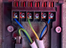
The original Danfoss WC4B wiring:
WhatsApp Image 2023-10-07 at 21.40.52_d39db413.jpg

img_3050-jpg.890884

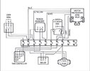
The programmer wiring and diagram:
WhatsApp Image 2023-10-07 at 20.40.12_11888164.jpg

programmer-jpg.180362


And the following is how I ended up connecting it after following the guides. I'd like to mention that it partially works, depending on how I play with the wiring in pos 2-3-4 of the central wiring I get to turn the boiler on for CH but doesn't turn off, and HW doesn't seem to work at all.

For the Heatlink call-on-heats I pulled Live with another wire from central which I don't think should be a problem (rather than bridging from L to 2 and 5):
WhatsApp Image 2023-10-07 at 20.40.00_ee136a78.jpg


Current central:
WhatsApp Image 2023-10-07 at 21.55.21_af791135.jpg


Can someone please help me figure it out? I think the problem lies in the mess of connections in pos 3 and 4 and someone messed with the original Danfoss bridges slightly (missing 12 to 13 from what I can see the default was online). A wonder it used to work somehow. I can hear the 3-port valve moving and it manages to do mid-port HC and HW.
 
Have you mixed up the wires? Some idiot has used the cpc/earth as a live (hot water off) which could become confusing not to mention against wiring regs.
 
Have you mixed up the wires? Some idiot has used the cpc/earth as a live (hot water off) which could become confusing not to mention against wiring regs.
Nope,
The previous cowboy ran out of wire or colors and decided to use a standard 3 way mains cable. That earth you see far right at 12 is DHW Off on the original programmer.
 
I wonder why you have introduced more cables to the Heatlink?
The system was working with the two cables that were there before.
This should have been a straight swap of those wires to the HL, without touching the wiring centre.
Can you put the old system back, check it works, and then we can help you start again?


Some idiot has used the cpc/earth as a live (hot water off) which could become confusing not to mention against wiring regs.
Calm down! ;)
The usage of oversleeved CPC was only explicitly banned in 2022! :)
 
Ok, what I can’t help wondering, why there is a brown in 6, with the same cable with green/yellow wire going to earth and the blue going nowhere.

The brown in 6 goes to grey from the 3 port valve, and the GY wire is 12 as we discussed above, and the Blue in 13 is on the same cable.
The blue you're probably seeing going nowhere at the bottom is the cable I used to pull live into the heatlink which I've only used Earth and Live from (B and GY). But tbh I might get rid of this for simplicity.

I'm kinda glad judging from your questions I am not the only one disappointed with the way I found this box...
 
1696715188555.png

I would expect you will need to link 2 and 3, and 8, 9, 10, 11 will go to Nest and also earth. The wires which were in 2 and 3 may be able to be reused in T1 and T2 of the Nest to send 12 volt to the controller/thermostat. However you will need to use a meter to check not connected to 230 volt, and there are some clear errors in the wiring 1696714441015.png green/yellow should only be used to earth, so it will need another core, the basic diagram is here 1696713571793.jpeg but the numbers of the wiring centre are clearly not the same, I would use the colours for the motorised valve to help as they are fixed, but other cables one can't rely on colours.
 
Thank you for that input. It helps that my thermostat has a base and will be kept indoors so no T1 T2 wires at all. It's all already connected and controlling stuff, just not very well as HW not working and depending on how I play with 2 and 3 it doesn't turn off the boiler once it turns it On.

You're probably right, I should literally re-wire it from scratch, following the diagrams. I am slightly worried I would screw it up but I guess having all these pictures to revert wouldn't be too bad. There's a lot of wires in that 3 and it makes it hard to add anything else to it, and I don't particularly understand why they're all there in terms of logic. There's a pair of wires going to a Honeywell FrostStat thing which I am not sure if it's even doing anything or is necessary in this system because the Nest has protection integrated into the software once it gets to 4C or below, and Away setting set to 17C.

I don't understand where CH is turned Off from, as there doesn't seem to be a position for that, only HW Off.
 
Last edited:
I wonder why you have introduced more cables to the Heatlink?
The system was working with the two cables that were there before.
This should have been a straight swap of those wires to the HL, without touching the wiring centre.
Can you put the old system back, check it works, and then we can help you start again?


Calm down! ;)
The usage of oversleeved CPC was only explicitly banned in 2022! :)
Sorry, I missed this reply. This is an old installation indeed, not sure how old, but definitely before 2022 haha.

The reason I didn't do a straight swap is because there was a separate programmer and thermostat there previously. This was even more confusing as the thermostat had no control over the HW at all. Here's a pic of what I started with, and there's yet another small box out of the picture for a Honeywell FrostStat thing:
WhatsApp Image 2023-10-07 at 23.32.35_76180a01.jpg


By far my biggest grief is figuring out how this system is controlling the HW On/Off, while controlling the 3-way valve for it, because of the inter-dependencies created at the wiring center, which seem to have been done carelessly. For example, 12, the Live for the Boiler isn't used for that, and instead seems to connect to Grey on the 3 way valve
 
Last edited:
After looking at the pictures again, and if I understand correctly, the only changes you have made to the wiring centre are:

To link out the stat on the left side - so the blue (marked black) call for C/H, connected to 13 has been linked to the white/brown in 4.

And to bring another cable to provide Live and earth to the HL.

If these are all the changes you've made (and I think everything else looks ok), I would definitely do this...
The blue you're probably seeing going nowhere at the bottom is the cable I used to pull live into the heatlink which I've only used Earth and Live from (B and GY). But tbh I might get rid of this for simplicity.

And if this doesn't improve the situation; as earlier, I would suggest swapping the previous thermostat back - that may prove that your linking out of the stat was incorrect, or something else i.e. the heatlink may be faulty.
It's often easier when DIYing electrics to take one step at a time, rather than attacking the wiring all at once!
 
So I did some tidying up to help myself and make it easier for people to help me as well hopefully:
WhatsApp Image 2023-10-08 at 00.29.18_51dfcff9.jpg

Wiring Central:
WhatsApp Image 2023-10-08 at 00.29.23_7be781c5.jpg


I took out the separate live cable to Heatlink and just wired it in serial from its own L. I ran a single Earth wire to it that I took out of a cable.
I linked 2 and 3 together. Results are as follows:
CH - works fully. Incl. turning valve, pump turns on and boiler turns On and Off (from Thermostat).
HW - valve turns, pump starts going, boiler doesn't fire.
Manual button - moves valve to mid, pump goes, boiler doesn't fire (despite the lights on the Heatlink turning On).

This is kinda the opposite of what I would like as I'd prefer if the HW worked for now at least instead of CH :LOL:.

Oh and I taped in Red the erroneous Earth cable that goes to Brown 12. Hopefully that helps with misunderstandings.

It seems to me someone did it this way so as to specifically accommodate for that Honeywell FrostStat thing. So they commoned lots of stuff for that to turn on in case it detects freezing temps. I am tempted to take that out as well and rewire everything as per the Danfoss Diagram. Would you advise that? Should I rely on the Google Nest software extreme temp. failsafe?
 
Again, your wiring looks ok (although the camera angle on the nest is deceptive!).
For a quick check, without the hassle of swapping over the old controller, just link 5 and 6 on the HL. If the system fires up for hot water, the HL may be faulty - this isn't unknown.

But as you suggest the midposition Valve moves, but the system doesn't fire, could it be a coincidental microswitch failure on the valve?
...this is all assuming you haven't made any other changes to the wiring centre!

Just to note, the earth connection for the HL is only required if you are using T1 and T2 to power the Nest Thermostat.
And, please use the cable grips, when everything is up and running! :)
 
Last edited:
I pretty sure the HL works fine as when I turn the HW Boost On, the relay goes for the Pump and the Valve switch moves (audibly). Just the boiler doesn't fire up. It did before when I used Manual but it was in a different configuration which wasn't turning the boiler off. My brain is fried atm. Is it advisable to rewire it all by the book using the Danfoss Diagram? And to disregard the Honeywell FrostStat? Unless someone can figure out what I'm doing wrong.
 
Back
Top