Buderus Logamax wiring

Joined
13 Feb 2017
Messages
7
Reaction score
0
Country
Greece
Boiler: Logamax UO52- 28K
Thermostat: Buderus RC 100 (24v)
Everything works fine!
Trying to change the thermostat for a programmer (Salus) but it will not control the boiler. I naturally assumed it was a Salus problem, but it is not . . after much testing and head-scratching I have discovered that with the existing thermostat if I turn the power off to the boiler then disconnect the thermostat then turn the power back on again the boiler runs continuously and takes no notice of the thermostat. However IF i just disconnect the thermostat without switching the power off the thermostat controls the boiler just fine.
Hmmmm . . . the thing is that I would prefer to switch the power off to the boiler before connecting the Salus (I know it is only 24v, but I am a cautious sort of guy and there is a 240v supply to the Salus in close proximity!). But if I disconnect the boiler and install the Salus then the boiler runs continuously and takes no notice of the Salus (just like the RC 100).
It seems pretty clear that it is a boiler wiring thing.
Can anyone offer advice on how I can change the RC 100 for a Salus without doing so whilst the circuit is live.
 
I cant find the instructions for your stat but I would imagine its connected to a bus system and not a simple on/off, that's why your having problems with it, if you have the instructions there should be a 24v connection for your salus in the boiler.
 
Your existing RC100 thermostat is probably using the 2 wire Bosch EMS bus (Energy Management System). This allows the thermostat to take control of the boiler heating temperture etc. In my experience the Buderus thermostats are horrible to use and I've had customers rip them out for something simpler.

The Salus programmer is probably just a simple relay switch. See if the boiler has terminals for connecting standard on/off controls.

AFAIK that model of boiler is not sold in the UK so there's little documentation here.
 
Although I have the purported wiring diagram for the boiler (in Greek) it does not seem to correspond with what is actually there! Currently the thermostat wires go to the 24v bus and I am a bit reluctant to change them from terminals that SHOULD be 1 and 2 but are marked 'BB'.
 
You stand every chance of destroying the board without knowing exactly where to connect an on/off thermostat. It may of course not be possible...the Dutch (and Germans) are very misguided and obsessed with energy efficiency and it may not be possible to have such basic controls.
 
Yes, thanks for that. Clearly the boiler responds happily to the existing 'simple' control of the RC 100. I think it would work okay with the Salus if I connect the two (24v) wires that the existing 'stat uses.
My problem is that if I turn off power to the boiler it fires up when I restore power regardless of what the thermostat is doing - indeed if I disconnect the thermostat wires the boiler still fires up when I switch the power on again. This is annoying because I am reluctant to wire in the new 'stat without powering down the boiler (from whence the 230v AC comes).
Unless anyone can crack this problem for me i will just have to be brave . . . .
 
Sure, but it won't be today. Thanks, I will get back as soon as I can get to the installation and take a pic.
 
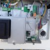
Okay, so at last I have a picture. Top left is the 230v arrangement. The mains power for the Salus is taken from terminals L and N (which are also used for mains power IN)
Top right is the 24v side. The connection to the roomstat are the two top wires (brown and green/yellow) at terminals BB, these were the wires to the RC 100 stat and I have not moved them.
Note also the link between terminals 8 and 9 on the orange connector. I have no idea if this is correct so have not moved it.
 

Attachments

  • IMG_2646.JPG
    IMG_2646.JPG
    237.8 KB · Views: 1,078
Several boilers use standard markings to identify the terminals provided for remote controls (Ls, LR and Ns). The terminals on the far left, and complete with the factory fitted standard link between Ls and LR, are marked in accordance with this:

In such cases, once the grey link is removed, then the wiring is:

Ls stands for 'Live supply' this is used to supply a live to the thermostat switching contact, in the case of Salus the 'Com' terminal [It can also be used for a permanent L if required]

LR stands for 'Live Return' this is from the thermostat switching contact, in the case of Salus the 'NO' terminal

Ns stands for 'Neutral supply' to provide a N for the remote controls if required.

However, unfortunately I can't advise you of what's involved in decommissioning the existing thermostat from the boiler wiring because I have never seen a Logamax.
 
Thanks, Stem. That is all pretty basic stuff. My problem relates to the strange way that the Buderus behaves when I either disconnect the existing roomstst or connect the new Salus. It fires up and keeps running.
I posted the wiring pic as another contributor suggested I should. I am entirely happy with the 230vac wiring and the 24v is unchanged. I just used the existing 24v to connect the Salus instead of the existing ( plus a 230v supply). The only thing that I can see and which I do not understand is the link on the orange connector.
 
A lot will depend upon how the present thermostat and 24v BUS system work. For example, I have seen some thermostats where the BUS sensor is an electronic device that generates an analogue signal relating to the room temperature which the boiler circuitry reads as a value and regulates the boiler temperature accordingly. Standard thermostats provide just an on or off signal and so wouldn't be compatible.

Of course. this may or may not be the case in your instance, but might be the reason it doesn't work when you connect it to the existing thermostat wiring.
 
I would disconnect the wires on the BB connections and take the link out of LS and LR, connect the wires from the salus com and nc and connect to LS and LR connections and see what happens, you cant cause any damage because there is no voltage on the salus , you are just connecting LS and LR when the stat switches.
 
It works!
My thanks for all the excellent suggestions. I did exactly as suggested - along with my own interpretation of the wiring diagram of the Salus. What I had not appreciated is that this Buderus uses a unique data language on the low voltage side (EMS) so only a Buderus 24v thermostat will work the boiler. The answer (of course!!!!) is to use the mains voltage side of the boiler connected to the mains voltage control of the Salus.
Great work folks - again my thanks from deepest Greece.
 
Back
Top