Confused with staircase 3 switch circuit

Joined
15 Sep 2022
Messages
6
Reaction score
0
Country
United Kingdom
Hi All,


Some weeks ago one of our ceiling lights stopped working.

It’s one of those where 3 switches operate it, in our main corridor.

With a multimeter I tested the fixture which holds 3 Compact Fluorescent Light Bulbs.

The bulbs themselves are all fine (tested in a different room).

Removing the fixture and exposing the cables I measured a strange voltage value… around 50V!!!???

I opened one of the switches and it was a 4 way. Opened a second one and also a 4 way. The last one is a 3 way.

The house is about 9 years old and this has worked since day one, not sure what happened.

Measuring the voltage on the 4 way switches shows a strange 147V. if I switch the switches (using their buttons) I can get up to 200V, yes, not higher than that. I tested this with 2 different meters.

Could one of the switches be faulty causing this? What else could cause this strange voltage reading? Nothing else was tripped nor behaving differently, just this particular staircase system.

Any idea of what this might be or tips to further diagnose?
 
At switch positions ,what / where are you taking the voltage readings from ( what conductors )
Have you taken voltage measurements on other circuits ,if so what voltages are present ?
Show us pics of light fittings terminal block/ wiring ,and one of the switches.
 
With a multimeter I tested the fixture which holds 3 Compact Fluorescent Light Bulbs.

The bulbs themselves are all fine (tested in a different room).
You tested the lamps, but not the fitting. It is likely that the fitting includes some components that make the CFL lamps work. There is probably a ballast and/or some HF electronics. It is more likely that something in the fitting has failed rather than the very reliable light switches.

So, before you go any further, Put your voltmeter on the power in connections to the fitting (between L and N). Have someone else run up and down the stairs turning the switches on and off and you should see a corresponding on and off on your voltmeter. If you do see this then its the fitting and not the switches.
You could just connect a standard mains lamp to the feed to the light fitting and see if that works ok.

Not sure about your voltage readings, as you haven't told us between which point(s) you measured the voltages. And digital meters can give strange results sometimes because of induced voltages.

Edit: You havent mentioned what sort of switches these are. You mention "buttons". Are they some sort of fancy switch?
 
IMG_1773.jpg
IMG_1771.jpg
 
1663266174692.png
It's this type of lamps and I did say: Removing the fixture and exposing the cables I measured a strange voltage value… around 50V!!!???
 
The fault is probably the neutral being open circuit.
That multimeter, like most of them, has a very high impedance input. Displayed voltages are probably due to cable capacitance and are therefore total nonsense.
 
One pic looks like you are measuring across 2 line conductors at the switch terminals.
The other pic, one probe is touching a connector block and it's not clear what conductors are in it ,are they earth conductors ?
 
1 way is on/off, 2 way is either or, 3 way have a centre position, 4 way likely rotary switch so has 4 positions, I am sure this is not what you are talking about, likely two 2 way switches and 1 intermediate switch, which is same as reversing switch.

In the main
two-way-plus-inter.jpg
this is the way we wire two way and intermediate switches, but not the only way it can be done.

Running two wires in close proximity to each other will result in some capacitive and inductive linking, so one will likely measure some odd voltages with a valve volt meter, or similar, likely a tester like this
1663266788318.png
will work better.
 
One pic looks like you are measuring across 2 line conductors at the switch terminals.
The other pic, one probe is touching a connector block and it's not clear what conductors are in it ,are they earth conductors ?
Sorry for the delay in coming back to you....

- correct. Pic showing 184.7 I'm measuring between the black and dark grey cables, both on the block
- Oh no, not earth conductors, I'm touching the brown wires and the dark greys (block). It looks like for those brown ones one is coming in and one out. These do not connect to any of the block terminals. Looks like the latter are just using the box to create an extension?

perhaps I need to try to draw a schematic for all three switches.

regards
C
 
1 way is on/off, 2 way is either or, 3 way have a centre position, 4 way likely rotary switch so has 4 positions, I am sure this is not what you are talking about, likely two 2 way switches and 1 intermediate switch, which is same as reversing switch.

In the main View attachment 279687 this is the way we wire two way and intermediate switches, but not the only way it can be done.

Running two wires in close proximity to each other will result in some capacitive and inductive linking, so one will likely measure some odd voltages with a valve volt meter, or similar, likely a tester like this View attachment 279688 will work better.
thank you very much with the explanation. The strange thing is that I measure also strange voltages at the end of the 2 wires where the lamp will connect. I will try to measure them again later when home and show pic here
 
thank you very much with the explanation. The strange thing is that I measure also strange voltages at the end of the 2 wires where the lamp will connect. I will try to measure them again later when home and show pic here
Yes, but you probably measuring through the lamp to neutral. As you are using a digital voltmeter this will pick up all sorts of stray induced voltages.
 
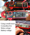
In school we are taught DC, and 50 Hz AC works in the main like DC, but not completely like DC. We get capacitive and inductive linking which gives what seems strange results. So unlike DC can detect AC with no contact testers. Multi-meter-small.jpg The three pictures show top NCV, the 4 bars means close or high voltage, as I move the meter jaws away from the source, the number of bars drops, but the Non contact voltage (NCV) is only looking at the line, there may be no neutral.

Next I am using leads, this shows voltage between the two probes, so is also measuring neutral.

The last is measuring DC across a battery.

The meter you show does not have a non contact function, neither for volts or amps, and many electricians think that is good, they hate the non contact tester, in the main some thing like this, 1669829445114.png and they clearly have their limitations, but so does the contact meter, you need a reference point. Before the non contact meter I often used the earth, but the supply voltage 207 to 253 can be displayed with a high ohms per volt meter in error.

In the old days using the AVO Mk 8 I would change range, if the voltages did not match, I knew it was capacitor or inductive linking, but today the AVO Mk 8 is a museum exhibit, at the price no wonder, so we need to learn how to use the new generation of meters.

Not only meters but all testers, including the non contact and the neon screwdriver, they all have a place.

In latter life I decided to do an 'A' level in physics, being honest I wanted the 'A' level maths, and it was nearly £200 to do that, and £10 if I did three 'A' levels. So I did physics as thought it would be easy, considering I already had a foundation degree in electrical engineering.

I was really surprised at the course, to put it simple, it was wrong, it showed diagrams of fluorescent lights I knew would not work, which resulted in my taking the rest with a pinch of salt. I watched as ½ the students ruptured the fuse in the multi-meters, and I questioned the training given.

I do not blame the students, or the lecturer although the latter could have done better, but it was the whole way the 'A' level was set out, A was suppose to stand for advanced, if the government think that is advanced, god help us.

The maths at least was good, that was what I wanted, but no wonder so many people have problems with simple AC theory with an 'A' level like that.
 
In school we are taught DC, and 50 Hz AC works in the main like DC, but not completely like DC. We get capacitive and inductive linking which gives what seems strange results. So unlike DC can detect AC with no contact testers. View attachment 287339 The three pictures show top NCV, the 4 bars means close or high voltage, as I move the meter jaws away from the source, the number of bars drops, but the Non contact voltage (NCV) is only looking at the line, there may be no neutral.

Next I am using leads, this shows voltage between the two probes, so is also measuring neutral.

The last is measuring DC across a battery.

The meter you show does not have a non contact function, neither for volts or amps, and many electricians think that is good, they hate the non contact tester, in the main some thing like this, View attachment 287351 and they clearly have their limitations, but so does the contact meter, you need a reference point. Before the non contact meter I often used the earth, but the supply voltage 207 to 253 can be displayed with a high ohms per volt meter in error.

In the old days using the AVO Mk 8 I would change range, if the voltages did not match, I knew it was capacitor or inductive linking, but today the AVO Mk 8 is a museum exhibit, at the price no wonder, so we need to learn how to use the new generation of meters.

Not only meters but all testers, including the non contact and the neon screwdriver, they all have a place.

In latter life I decided to do an 'A' level in physics, being honest I wanted the 'A' level maths, and it was nearly £200 to do that, and £10 if I did three 'A' levels. So I did physics as thought it would be easy, considering I already had a foundation degree in electrical engineering.

I was really surprised at the course, to put it simple, it was wrong, it showed diagrams of fluorescent lights I knew would not work, which resulted in my taking the rest with a pinch of salt. I watched as ½ the students ruptured the fuse in the multi-meters, and I questioned the training given.

I do not blame the students, or the lecturer although the latter could have done better, but it was the whole way the 'A' level was set out, A was suppose to stand for advanced, if the government think that is advanced, god help us.

The maths at least was good, that was what I wanted, but no wonder so many people have problems with simple AC theory with an 'A' level like that.
thank you very much for this information!!!
 
I suppose I must have missed that lesson.
I suspect like me, you have quite a few turns to the coil? Although I started school in 1956, I returned in 2006 to upgrade my education. Things have moved on, when I started the IEE was not really considered as a organisation which required following, but today the IET/BSi is considered as the be all and end all as to what is required.

1882 with the Rules and Regulations for the Prevention of Fire Risks Arising from Electric Lighting to 1992 with the BS 7671:1992 is a huge jump. By this time I was not even in this country, I returned to find electricians quoting BS7671.

It was 2004 before I went on a coarse to get my 16 edition, at that time considered as really the 17th edition which came out 2008 and yet another coarse and exam, as to if really required not so sure, as it seems since then the rules have upgraded many times.

So the comment "I missed that day in collage" rings true. Remembering every upgrade and when needs a computer of a brain.
 
Back
Top