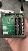
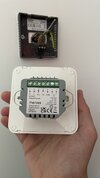
Danfoss Combi Boiler Thermostat to Meross Smart Thermostat

Joined
17 Nov 2018
Messages
25
Reaction score
0
Country
United Kingdom
Apologies I wasn't sure if this would be better in the Electrics or central heating forum.

I currently have a Danfoss thermostat which I wanted to switch out with the new Meross Smart one I purchased.
Thinking this would be an easy swap but I've discovered the Danfoss seems to be battery powered so I'm confused in regards to which wires would go where on the new Meross which requires a powered connection.

I understand the COM and NO connections are from the boiler but am unsure if the grey sleeved wire that's not connected to anything could be either a live or neutral that I could connect to the Meross.

Any advice would be appreciated.

Wires in wall:
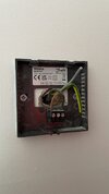
IMG_8554.JPEG

Old Danfoss:
IMG_8556.JPEG

New Meross:
IMG_8555.JPEG
 
If you look carefully, you will see the wires go to terminals on the Danfoss thermostat marked COM and NO. The New thermostat also has terminals marked COM and NO. So the brown wire goes to COM and the black wire to NO as they do now.

As you say, the old thermostat was battery powered, and the new one is mains powered, so you need a 230V supply for the new thermostat connecting to terminals marked N and L. This should come via the same 3A fused connection unit that supplies the boiler.

Now it may be that the old thermostat is wired using 230V switching and the brown wire in COM is actually a Live. In which case it can be linked to the L as well, and if you can find the other end of the grey wire which may also not be connected to anything at its other end. It could be used to provide the Neutral connection. It you have a multimeter (or know someone that has) and are competent in using it you can check if the wire in COM is a live or not.

A word of caution though. Some boilers use 24v for the thermostat control, others use 230V and others have the option of either. So you do need to check. If you have a system where the thermostat is connected to a motorised valve they will be switching 230V

No mention of an existing programmer / timeswitch anywhere, which if you do have may also require attention.
Thanks for your detailed response!

Likely I’m being stupid asking but how would I connect the current brown COM to BOTH the new COM and the LIVE at the same time?

Also, regarding the unconnected grey wire, assuming this is a neutral can I just strip some of the sleeve at the end and connect this to the new thermostat as is?
 
how would I connect the current brown COM to BOTH the new COM and the LIVE at the same time?

Like this by adding a short link wire between L and COM.

Screenshot 2024-07-15 091706.jpg


I assume you have determined that the brown wire is connected to a live, as per my first post. If you haven't, don't assume that the brown wire is being used as a live, it may not be connected to 230V L at its origin, it may be connected to 24v.


Also, regarding the unconnected grey wire, assuming this is a neutral can I just strip some of the sleeve at the end and connect this to the new thermostat as is?

Yes that's how the connection would be made, but. the wire may be unconnected at its other end. You can't assume that it is connected to a neutral.
 
This should come via the same 3A fused connection unit that supplies the boiler.
Stem is correct, however I have seen many where the supply did not come from the boiler supply, very common when people install Nest thermostats that the USB power does not come from the boiler's FCU.

The main problem, is if the thermostat is 230 volt AC, that when there is a fault, the thermostat can end up by-passing the fuse. So with many boilers even the boiler's FCU is not any good, it needs to get the 230 volt from within the boiler, so the boiler's fuse is not by-passed. This then causes a second problem, some manufacturers have seen fit, to put the supply junction box where room seals are broken to access it, so needs someone with the test equipment and knowledge on how to use it.

So we are left with a risk assessment, which method presents the greatest risk, opening the boiler to connect a neutral, or using an independent supply? I know my boiler, the panels are not sealed, pity, as a strong smell of 28 sec gas oil. And I know my mother's gas boiler was not sealed, there was an open space under the boiler, so no attempt had been made to seal it from the room.

But we have no idea as to if your boiler is room sealed where the electrical connections are, or for that matter if the cable even goes to the boiler, it may go to a wiring centre.

So my assessment not being on site, so can't get the info, is better to use an independent supply just like the Nest users use. OK, their step-down transformer may be independent to the thermostat, but they are still using a different supply.

Best would be to use a thermostat which is battery powered, like the Nest e, however the Nest e does not connect to TRV heads, but neither does the Merose so no advantage using Merose over Nest e, and the Nest e is a direct replacement for what you have.
 
I have seen many where the supply did not come from the boiler supply, very common when people install Nest thermostats that the USB power does not come from the boiler's FCU.
Which is fine as the voltage being applied to the thermostat via the USB is only 5V.

Screenshot 2024-07-15 123113.jpg


Thermostats such as the Merros thermostat that the OP has require 230V for its operating power.
 
It's not something I would recommend.

you need a 230V supply for the new thermostat connecting to terminals marked N and L. This should come via the same 3A fused connection unit that supplies the boiler.

This statement, or a variant of it can be found in most boiler installation manuals. Here's one example from Vaillant.


11.jpg
 
I believe our boiler is a Baxi Platinum Compact Combi.

Looking at the service manual and searching for "thermostat" it sounds like it may indeed be a 230V connection?
Section 8.1.1

It also states that "The 230V switched signal for external controls (frost thermostat —
room thermostat — timer) must always be taken from terminal 2 at
the boiler. Live, Neutral and Earth to power these controls must be
taken from the Fused Spur."

Does this mean I am not supposed to use it to power the Meross, or would it not matter?
 
From the manual, as you say, boiler terminal 2 (from wire bk 2 in the diagram below) does provide a Live, so should be presently connected to the existing thermostat COM . The wire in terminal 1 (from wire b1 in the diagram below) should be connected to NO. So you should have as per the below. Except that in your case there is presently no Neutral connected to the existing Danfoss thermostat.

terms.jpg
nom.jpg


From the instructions you posted.

Screenshot 2024-07-18 094821.jpg


In the case of the 230V L coming from terminal 2 (bk 2) it is fed from the Fused Spur, as it will be isolated when the Fused Spur is switched off.
 
Back
Top