Electrical certification on UK home automation / lights - sonoff

Joined
13 Feb 2014
Messages
151
Reaction score
1
Location
Buckinghamshire
Country
United Kingdom
Hi:
I've been doing some minor home automation at my home but I'm considering taking the next step and adding automation to my lighting circuits.

I'm not a fan of smart bulbs, they are a v expensive approach and it just makes a lot more sense (to me at least) to put the "smart" into the fixed circuits or switches rather than the bulbs which have a shorter lifespan and thus the long term total cost is v high.

I've been looking at sonoff basic wireless devices as the price point is very attractive and it will connect with my home automation setup.

I've seen two approaches that could work in UK wiring systems:

Approach 1:
Set-up sonoff adjacent to each ceiling rose junction box in a circuit and use the GPIO pin to take a low voltage signal from the switch to maintain the ability to use the original switch alongside the home automation capabilities
This uses as much of the existing wiring already in place but it does mean that the sonoff devices are all hidden under floor boards all over the house rather than one central place.

Approach 2:
Rewire the circuit such that each light has a dedicated cable from a centralised switch board, sonoff devices are all located in the centralised switch board, wall switches would then need to be turned into ethernet or wireless switches to signal back on/off commands via home automation
This centralises the sonoff devices in a more easily accessible location but this requires a rewire and the use of a lot more cable than normally required in a traditional setup.

Q1: any thoughts on the approaches / is there an easier way?
Q2: Does any of this allow a homeowner such as myself to achieve a project like this which passes IET Wiring Regulations / Edition 18? If so, how do you find electricians to commission and sign off the paperwork?

Thanks in advance for your help
 
Option 1 could be used, however the devices must remain accessible for maintenance, and they must also be installed into suitable enclosures with proper cable restraints and so on.

The other and rather more likely way is to do option 2, and also put cables from each switch position to the central panel.
Wireless efforts should never be used if wire is a possibility, and as option 2 needs a total rewire anyway, the extra cables from the switches to the central position will make little difference to the cost or installation time.
More expensive systems are wired with the switches or other controls on bus style wiring, which typically loops from the control cabinet to each switch position in turn.

Anyone competent can design and install circuits in accordance with BS7671 (wiring regulations).
If you want someone to do some of that for you, the only sensible choice is to find someone before any work is started, and establish exactly what they will do and what you will do.
Installing a pile of wiring and expecting people to turn up and connect it is a recipe for expensive disappointment, as most won't want to get involved with things at that stage.
 
Option 1 could be used, however the devices must remain accessible for maintenance...

Yes - they won't be which is why I am nervous about this approach. Especailly as I want to periodically check these devices for early signs of over heating or other failures.

More expensive systems are wired with the switches or other controls on bus style wiring, which typically loops from the control cabinet to each switch position in turn.

This sounds v interesting! How is this done? Ethernet cables with a basic micro controller at each switch so that each switch can be addressed individually on the bus? any pointers on where I can read up on this would be great.
I was thinking whether it would be possible to use ethernet for low voltage circuit from the switch board, where one of the wires is ground and the 7 others can be terminated at the end of each individual switch, bringing that all back to a micro controller back at the switch board to integrate back into the home automation system. But I'm not sure whether crosstalk on UTP cable might be an issue, or even if low voltage on long cable runs would work. While not really a bus it would save on cable!

If you want someone to do some of that for you, the only sensible choice is to find someone before any work is started, and establish exactly what they will do and what you will do.
Installing a pile of wiring and expecting people to turn up and connect it is a recipe for expensive disappointment, as most won't want to get involved with things at that stage.

Totally agree, I just want to get my knowledge up and have some concepts on how I may like it done before having that chat. I hope however I can do the install and the commissioning is more testing and paperwork. I'll see where I get to on that when I am at that stage.
 
For what it is worth.

All the lights in my cottage are wired to one of two banks of relays. This is one of them.

upload_2019-4-22_8-43-8.png


The relays are controlled by a bespoke micro-processor based controller. All wiring compliant with BS7671

Inputs to the controller are 12 volt 24 mA circuits connected via alarm type cable to ELV switches.

upload_2019-4-22_8-48-27.jpeg


The primary reason for ELV switches and relays was to avoid chasing into wattle and daub walls for switch drops using 230 volt cables.

However the engineer in me then took over and added several useful functions such as timers, security lighting and ringing a door bell after dark turns on the relevent porch light.
 
Yes - they won't be which is why I am nervous about this approach.
That won't comply with BS7671, so forget that option.

This sounds v interesting! How is this done?
Documents from one manufacturer of such things who actually makes the information available to all: https://www.loxone.com/enen/kb-cat/all/
Different manufacturers systems are generally incompatible, so that information only applies to them, however the basic principles are similar for all.
 
Shelly 1 behind the ceiling rose? I have 4 of these now like this. Means the light switch still works too! I have 4 more on the way. I have also flashed these to tasmota and use them with home assistant.

I use a sonoff via low voltage to a light switch but only in the loft. You will need to flash it with tasmota or esphome etc to make this possible.
 
For what it is worth.
All the lights in my cottage are wired to one of two banks of relays. This is one of them.
This looks great thank you. What relays are you using? Sorry I can't tell from the photo.

That won't comply with BS7671, so forget that option.
Documents from one manufacturer of such things who actually makes the information available to all: https://www.loxone.com/enen/kb-cat/all/
Thanks - I am going to take some time later to read over.

Shelly 1 behind the ceiling rose?
I saw a great comparison between these and the sonoff. Where is the best place to get these in the UK?

Thanks all!
 
Personally if I rewired my house again all switches and ceiling roses would go back to a central location. This would then future proof it and allow for easier upgrades/repair work
 
Personally if I rewired my house again all switches and ceiling roses would go back to a central location. This would then future proof it and allow for easier upgrades/repair work

I'm going to look at both options as I am very tempted to do the rewire but I've decorated some of the rooms and I don't want to mess those up. Keen to hear about @bernardgreen relays and any more info so I can weigh things up.

Thanks all -so very useful!
 
What relays are you using?

The relays are Finder Part Number 40.31.7.012.0000 and the sockets are Part Number95.83..3

Many of the lamps are used in pairs with three relays to achieve a dim function by running them in series.
( Yes, sadly it does require the lamps to be rough service incandescent lamps )

upload_2019-4-22_18-10-13.jpeg
 
ok I have some reading and investigation work to do at home to see if I can do a rewire. I'll likely come back here with more questions! Thanks v much for all the help so far.
 
This is the prototype of the controller board, 32 opto isolated inputs along the bottom edge and 32 relay drivers on the right hand edge.
upload_2019-4-22_18-20-42.png
 
Hi:
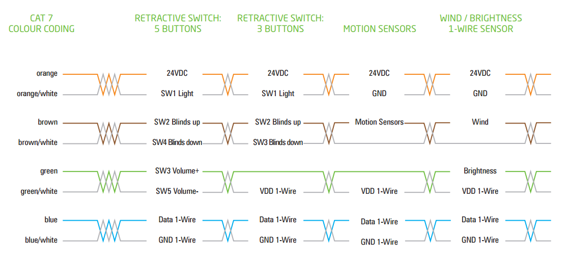
Thanks to the link by @flameport I did some research and found this interesting diagram.
In principle these systems use ethernet in the star/bus topology to the switches by using the wires in a proprietary manner. Loxone approach shown in the diagram below.
one wire is used for data but most are simple power signals.
A question that comes to mind:
I understand commercially why companies would go down the propitiatory route but are there also mainstream open standard light switches that exist that are IP based using Ethernet (not wireless) and possibly even powered using PoE?
This doesn't solve the very common challenge @bernardgreen that traditional cables are sunk into walls but assuming a rewire situation....

EN_KB_Wiring_CAT7_Colours.png
 
Last edited:
This is the prototype of the controller board, 32 opto isolated inputs along the bottom edge and 32 relay drivers on the right hand edge.
Did you make that yourself? that's brilliant. you mentioned in an earlier post a micro-processor based controller, basic question but is that this?
 
Yes the controller is all my own work. From concept through to final design,

Based on a MicroChip 18F2620 processor and programmed in assembler language. Iam resisting the temprtation to add a couple extra funtions.

are there also mainstream open standard light switches that exist that are IP based using Ethernet (not wireless) and possibly even powered using PoE?

There are some "standards" using a two wire bus with data and power for the bus interfaces on a single pair. The down side is the need for some "intelligence" in the bus interface at each node to recognise address / command packets and transmit reply packets.

OPne of the earliest of these basic "standards" was first seen in the late 1960's. The bus is supplied with nominal 24 volts DC and each node regulates this down to 5 volts to power the nodes' bus interface. If the bus voltage is above 15 volts then the data state is binary 0. When a node is transmitting a packet it pulls the bus voltage down to 9 volts for binary 1 and leaves it at <15 volts for binary 0. The 9 volt binary one signal is high enough for the nodes to maintain the 5 volt supply for their bus interfaces.

This simple and effective system was "adopted and improved" in 1996 by the OpenTherm group, Read more HERE . The "improvements" turned a simple system of data and power transmission that any one could use into an overly complicated system that can only be used by members of the OpenTherm group
 
Back
Top