Galaxy Dimension zones High Resistante

Sor

Joined
15 Dec 2017
Messages
43
Reaction score
1
Country
Portugal
Hi guys.

I've been having some faults with a Galaxy Dimension panel (installed March 2018):


- Fault in DualTech detector (onboard RIO 01 zone nr. 1011), on march 2020.
Option 21 showed last 13 days high resistances below 1200 Ohm, but high resistance on the day of the alarm (1296 Ohm). No problems before or since then.

- Alarm with smoke detector (offboard RIO 02 zone nr. 2021) on January 2021, no apparent reason.
Option 21 on the day of the alarm showed last 13 days with resistances OK (989-1036 Ohm), but high resistance on the day of the alarm (994-1296 Ohm). No problems before or since then.

- Aux Tamper Fault, only once, on February 2021, never before and never after. I did nothing to resolve it, it simply never happened again.


Option 21 for last 14 days shows that 8 zones (smoke and DT detectors, these DT are from different brands) register occasional high resistances, almost 1300 Ohm, but normally are OK.

Since these are both onboard zones and offboard (RIO 2 and RIO 3) zones, different detectors, I think it is likely the problem comes from the panel reading the resistances.


Can anyone advise me how to troubleshoot this?
Is it normal to have a high resistance only occasionally?


Thanks for any help.
 
Since you're seeing issues with off-board devices, I would check that the power rails are okay and perhaps suspect the wiring - long CCA runs ?

Is the battery okay, or is it loading the panel down ? Check in diagnostics 61.1 for power (press the hash key to step through the power diags).

There was a firmware update to only log marginal high res to engineering logs, but the resistances are probably on the high side, so the panel is doing its job. I would update to 7.04 anyway.
 
Thank you GalaxyGuy.

I have finally looked everything you said. But I have issues with on-board devices as well, as I wrote on my previous post: zone 1011 and Aux Tamper fault.

Power rails seem to be Ok, screws all tight.
I do not use CCA cables, only copper.
Distances to devices are not that long. Maximum around 30m, most no more than 15m, some only around 5m.

RIO 3 and Aux Tamper loop are the same that I had with the old Galaxy 16+ that this Galaxy Dimension replaced. They worked just fine for 20 years without a single fault or false alarm. The difference is RIO 3 has now an external PSU.
Only RIO 2 is new.

Both RIO 2 and 3 are only 3m apart from the main panel. They have an Elmdene power suplly. Therefore, I cannot test them with option 61.

RESULTS of Option 61 Diagnostics:

3. RIO Comms
Modu 100: 13,78V
Modu 101: 13,78V
Modu 202: 100% 13,88V
Modu 203: 100% 13,80V

4. PSU Comms
Results are OK, including the battery, but as I mentioned, that is only for on-board battery.


How can the update of FW help with these issues?
I am reluctant on having the cost of updating if the problem is with the main panel; in the end I might have to replace it anyway, even after an update, right?
 
Sorry, yes I should have re-read.

When you display->zones and press the hash key for zone 1011 what resistance is it showing normally ? If you replace the wiring at that zone with a 1k resistor, does it then read 1k?

If you can start to diagnose each issue, it may give a better clue as to it being a panel or sensor/wiring issue.
 
Whenever I check the problematic zones resistances they seem to be Ok, around 1000 Ohm.
But if I check the min and max resistances for the past 14 days, sometimes I find one day with a max very close to 1300 Ohm. Min are always Ok.

So I can replace the zone wiring with a 1K resistor and check every 2 weeks for some time. If the problem persists, then I have a panel issue, right?
 
Yes, if you have a spare zone, then move the detector to it and place a resistor in 1011. An installer would normally just replace the panel PCB to start eliminating components of the system, but if you don't have a spare board, then you'll need to test the zones.
 
I've been trying to find a pattern of the problem, but it's not easy.

Things I think that are strange:
- Min resistances of distant (30m) detectors being equal to min resistances of spare zones closed with 1k resistor on the board.
- Min resistance of spare zone closed with 1k resistor, normally changing between 984-1010 Ohm, one day having a Min. resistance of 863 Ohm.
- One day the Min and Max resistances of a detector zone (last 14 days history) was -----. I've found that to happen either when a zone is constantly open (constant infinite resistance) or the zone is constantly closed with a shunt (constant next to zero Ohm resistance). Never happened again.
- One day, two fire detectors (onboard zones) were constantly setting the alarm off, one after the other, for about 1 hour. I had a hell of a time to succeed entering engineer mode and changing the function of those zones to Spare, because the alarm was always setting off (fire zones). That was more than a year ago. That day, the resistances were up to 1308 Ohm, but I've been reading those zones resistances from time to time since then, never happened again.
- Zones (both onboard and offboard RIO's) that normally have resistances OK, sometimes (a single day or some days, but then, it might be back to normal for quite a long time) have very high resistances, next to or even above 1300 Ohm, which is a big problem.


@GalaxyGuy, can you help with the following?

1. Are the zones resistances measured (calculated?) in the offboard RIO's and the information sent to the main board or the main board calculates the resistances from the information it gets from the RIO's?

2. A 1k resistor shows a resistante of 992-993 Ohm in the multimeter. That same resistor closing the loop of a spare zone in the board is constantly changing the resistance between 984-1010 Ohm. Other spare zones with a 1k resistor normally read resistances between 989-1026 Ohm in the last 14 days.
Is this normal, such a wide range of readings from the board, compared to the multimeter?

3. Would a firmware update improve the situation in anyway?

4. I've replaced some 1k resistors with 910 Ohm resistors in the detectors. It seems to help, those zones have not reached more than 1250 Ohm, but the problem of high (though not so high as before) resistances persists.
Any problem with this approach that I'm not seeing?

Thank you.
 
To measure a resistor it has to be out of circuit and not connected to anything other than the meter.

When the resistor is in circuit the measurement will be affected by the connections to other components and the voltages on those components,
 
To measure a resistor it has to be out of circuit and not connected to anything other than the meter.

When the resistor is in circuit the measurement will be affected by the connections to other components and the voltages on those components,
Yes, I did just that. The resistor measured with the multimeter has a stable reading, +- 1 Ohm. But once I use that resistor to close a spare zone, its reading in the panel has a wide range, between 989 and 1026 Ohm. Is that normal?
 
Can you double-check that you only have A+B and 0V connected to your power RIO? You should not connect panel +12V to power RIO +12V as that will cause all sorts of power problems.

1. Are the zones resistances measured (calculated?) in the offboard RIO's and the information sent to the main board or the main board calculates the resistances from the information it gets from the RIO's?

>> The ADC conversion is performed internally to the RIO circuitry and sent digitally to the panel.

2. A 1k resistor shows a resistante of 992-993 Ohm in the multimeter. That same resistor closing the loop of a spare zone in the board is constantly changing the resistance between 984-1010 Ohm. Other spare zones with a 1k resistor normally read resistances between 989-1026 Ohm in the last 14 days.
Is this normal, such a wide range of readings from the board, compared to the multimeter?

>> This seems like a power problem. The ADC and double-balanced circuits have a reference voltage. If the reference voltage is incorrect or not stable, then the conversions will not be correct.

3. Would a firmware update improve the situation in anyway?

>> I think I commented on this before. I don't think your issue will be fixed with the firmware update, but it may be masked.

4. I've replaced some 1k resistors with 910 Ohm resistors in the detectors. It seems to help, those zones have not reached more than 1250 Ohm, but the problem of high (though not so high as before) resistances persists.
Any problem with this approach that I'm not seeing?

>> No problem with it, but it's not fixing the source of the issue. To debug this, you should disconnect the external devices (RIOs Etc.) and run with resistors in all zones and test for stability.
 
  • Thanks
Reactions: Sor
its reading in the panel has a wide range, between 989 and 1026 Ohm. Is that normal?

Yes

The meter measures resistance by putting a fixed known test current through the resistor and measuring the voltage this current creates across the resistor produces a result that indicates the resistance of the resistor. Resistance = Volts divided by Current ( Ohms = Volts / Amps )

The panel will be putting some current through the resistor and this current will add to or subtract from the test current thus affecting the reading.
 
  • Thanks
Reactions: Sor
Can you double-check that you only have A+B and 0V connected to your power RIO? You should not connect panel +12V to power RIO +12V as that will cause all sorts of power problems.
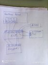
I believe I have it right (first attached diagram).

I do not have the 0V of the External PSU directly connected to the 0V of the panel, only via the RIOs.
1) But that is the same, right?

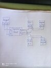
The layout of my system is in the second attached diagram.
I do not have 680 Ohm EOL resistors in the end of the lines (keypads) because the lines are maximum around 30 m long, but I have removed Link LK5 (page 2-8 of the Manual).
2) Does this look OK?

4. I've replaced some 1k resistors with 910 Ohm resistors in the detectors. It seems to help, those zones have not reached more than 1250 Ohm, but the problem of high (though not so high as before) resistances persists.
Any problem with this approach that I'm not seeing?

>> No problem with it, but it's not fixing the source of the issue. To debug this, you should disconnect the external devices (RIOs Etc.) and run with resistors in all zones and test for stability.
"... disconnect the external devices (RIOs Etc.) and run with resistors in all zones and test for stability.", including sounders, keypads, detectors, voice communicators?
3) In short, leave just the panel with zones with 1k resistors across and one keypad to check things out?
Do I need to reconfigure anything after removing the periphericals for debuging?
 

Attachments

  • IMG_20230401_165535.jpg
    IMG_20230401_165535.jpg
    101.1 KB · Views: 88
  • IMG_20230401_175224.jpg
    IMG_20230401_175224.jpg
    100.9 KB · Views: 116
1. Are the zones resistances measured (calculated?) in the offboard RIO's and the information sent to the main board or the main board calculates the resistances from the information it gets from the RIO's?

>> The ADC conversion is performed internally to the RIO circuitry and sent digitally to the panel.
So, if I have the same high resistances issues in both the onboard RIOs and the offboard RIOs, it is unlikelly that the problem comes from the Galaxy Control Panel, is that right?
 
Yes, but this seems to be a power issue. On your diagram you show a separate power supply. Is that a power RIO ? To debug this, you can try disconnecting the power RIO and leave the panel separate.
 
It is a Elmdene Power Supply, for the two offboard RIOs that I have, an external sounder and a landline voice communicator.

The voltages on those RIOs (Option 61 - Diagnostics) were a bit higher (RIO 2 = 13,96V; RIO 3 = 13,80V) than the voltages on the onboard RIOs 0 and 1, which had voltages of 13,76V, but it seems to me that is not a problematic difference.

I didn't shut down the Elmdene Power Supply because it also supplies an external sounder. But I disconnected RIO 3 from the pannel and changed the power supply for RIO 2 to Line 2 of the pannel. So now I have RIO 2 directly connected to the pannel, independent of the external PSU (Voltages now are RIO 0 = RIO 1 = 13,71V; RIO 2 = 13,72V).

I did this because there are more zones with higher resistances in RIO 2 and 3. The problem persists. One of the zones in RIO 2 already had a 1157 Ohm resistance after I changed things.

I can exclude the Elmdene PSU as the source of the problem this way, right?
 
Back
Top