Hi,
I’m trying to get my head around the plumbing in a new house. I intend to install a Tado smart thermostat system, but unlike my previous home, this one has two programming units and I am confused about how they interact and what one of them actually is for. The first part of my question is to understand the function of each pipe around my hot water cylinder and specifically the pump that is controlled by the secondary programming unit. The second part is to consider how best to install the Tado system.
There is a Gloworm Ultracom 38hxi gas boiler in the garage, and a Megaflo cylinder (I believe CL300, but I can’t see an actual model number, just a handwritten serial number) in the airing cupboard upstairs.
Next to the cylinder, there are two programming units. A Danfoss FP715 is the primary unit with timers for both radiator heating and hot water. I can see cables coming from it going to two separate (metallic) motorised valves, one (red) Grundfos circulator pump, and the indirect thermal controls on the Megaflo. This unit will be replaced by the Tado wireless receiver unit, so that it can control heating and hot water in accordance with the Tado app, coordinating with individual smart radiator thermostats for each radiator in the house (replacing their manual TRVs).
A separate Danfoss TS715SI unit has radiator timer controls only. It is connected only to a second (yellow) Grundfos circulator pump. My main concern is trying to understand how this interacts with the primary unit.
I have identified where the mains cold water comes in, through a 22mm (I think) pipe with a stopcock. It appears also to continue to another part of the house down a second 15mm (I think) pipe, before going up into the filling loop and a pressure vessel mounted on the wall, and into the water inlet at the bottom of the Megaflo.
I have also identified the hot water flow from the gas boiler, which is circulated by the red Grundfos pump and enters the Megaflo indirect heating coil, and also runs to a bypass pipe, a pipe labelled “radiators”, and a pipe I don’t understand (see below). One of the (metallic) motorised valves controlled by the FP715 primary unit sits on the pipe labelled “radiators” and the other on the flow into the indirect heating coil of the Megaflo, which makes sense.
I’ve also identified overflow pipes from both the Megaflo and the pressure vessel and the way in which the filling loop adds extra water to the boiler circuit.
However, two pipes/areas confuse me:

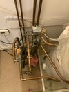
The blue line drawn here shows the mains cold water in and the yellow circulation pump that appears to be wired to the secondary programming unit, with red manual valves above and below it. It comes off the same pipe that is feeding the Megaflo inlet (bottom right). This pipe above the valves just above the stopcock, is warm to the touch (but not as hot as the hot water coming out of the top of the Megaflo ). I don’t understand what the yellow pump is for, or even whether the water is flowing “up” from the floor or “down” through it.
Can someone explain what’s going on here?
The second point of confusion is the red line. This is connected after the red circulation pump (which is connected to the primary programming unit), in parallel with the pipes going to the indirect heating coil in the Megaflo, a pipe labelled “radiators” and a pipe labelled “bypass”. This mystery pipe is labelled “TSAIR/RADS” (I think, it’s hard to read).
What is this pipe for?
And finally, the real exam question… if I replace the primary programming unit with the Tado receiver, what should I do with the secondary one that is controlling the yellow pump?
The Tado can open and close the motorised radiator and hot water valves, and determine the operation of the (red) circulator pump. One option would be to leave the secondary unit in “always on” mode (it is set to work on a timer currently) but this feels wasteful or worse. Each radiator will have its own motorised TRV, which will coordinate with the central Tado thermostat to turn on heating if one or more of them need it, but (unless I wire them in parallel?) Tado won’t be controlling the second pump. Another option might be to have a second Tado receiver unit replace the secondary controller, though I’m not sure if Tado supports this. Tado customer service is great at answering questions, but at the moment I don’t understand enough about what is going on to formulate a precise question to them.
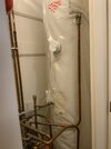
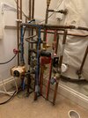
Thank you for any insight and advice! Some extra photos below, including a top-down view.


I’m trying to get my head around the plumbing in a new house. I intend to install a Tado smart thermostat system, but unlike my previous home, this one has two programming units and I am confused about how they interact and what one of them actually is for. The first part of my question is to understand the function of each pipe around my hot water cylinder and specifically the pump that is controlled by the secondary programming unit. The second part is to consider how best to install the Tado system.
There is a Gloworm Ultracom 38hxi gas boiler in the garage, and a Megaflo cylinder (I believe CL300, but I can’t see an actual model number, just a handwritten serial number) in the airing cupboard upstairs.
Next to the cylinder, there are two programming units. A Danfoss FP715 is the primary unit with timers for both radiator heating and hot water. I can see cables coming from it going to two separate (metallic) motorised valves, one (red) Grundfos circulator pump, and the indirect thermal controls on the Megaflo. This unit will be replaced by the Tado wireless receiver unit, so that it can control heating and hot water in accordance with the Tado app, coordinating with individual smart radiator thermostats for each radiator in the house (replacing their manual TRVs).
A separate Danfoss TS715SI unit has radiator timer controls only. It is connected only to a second (yellow) Grundfos circulator pump. My main concern is trying to understand how this interacts with the primary unit.
I have identified where the mains cold water comes in, through a 22mm (I think) pipe with a stopcock. It appears also to continue to another part of the house down a second 15mm (I think) pipe, before going up into the filling loop and a pressure vessel mounted on the wall, and into the water inlet at the bottom of the Megaflo.
I have also identified the hot water flow from the gas boiler, which is circulated by the red Grundfos pump and enters the Megaflo indirect heating coil, and also runs to a bypass pipe, a pipe labelled “radiators”, and a pipe I don’t understand (see below). One of the (metallic) motorised valves controlled by the FP715 primary unit sits on the pipe labelled “radiators” and the other on the flow into the indirect heating coil of the Megaflo, which makes sense.
I’ve also identified overflow pipes from both the Megaflo and the pressure vessel and the way in which the filling loop adds extra water to the boiler circuit.
However, two pipes/areas confuse me:
The blue line drawn here shows the mains cold water in and the yellow circulation pump that appears to be wired to the secondary programming unit, with red manual valves above and below it. It comes off the same pipe that is feeding the Megaflo inlet (bottom right). This pipe above the valves just above the stopcock, is warm to the touch (but not as hot as the hot water coming out of the top of the Megaflo ). I don’t understand what the yellow pump is for, or even whether the water is flowing “up” from the floor or “down” through it.
Can someone explain what’s going on here?
The second point of confusion is the red line. This is connected after the red circulation pump (which is connected to the primary programming unit), in parallel with the pipes going to the indirect heating coil in the Megaflo, a pipe labelled “radiators” and a pipe labelled “bypass”. This mystery pipe is labelled “TSAIR/RADS” (I think, it’s hard to read).
What is this pipe for?
And finally, the real exam question… if I replace the primary programming unit with the Tado receiver, what should I do with the secondary one that is controlling the yellow pump?
The Tado can open and close the motorised radiator and hot water valves, and determine the operation of the (red) circulator pump. One option would be to leave the secondary unit in “always on” mode (it is set to work on a timer currently) but this feels wasteful or worse. Each radiator will have its own motorised TRV, which will coordinate with the central Tado thermostat to turn on heating if one or more of them need it, but (unless I wire them in parallel?) Tado won’t be controlling the second pump. Another option might be to have a second Tado receiver unit replace the secondary controller, though I’m not sure if Tado supports this. Tado customer service is great at answering questions, but at the moment I don’t understand enough about what is going on to formulate a precise question to them.
Thank you for any insight and advice! Some extra photos below, including a top-down view.


Last edited:

