Hive Installation - Grant Oil Boiler, Potterton Programmer

Joined
7 Aug 2020
Messages
8
Reaction score
0
Country
United Kingdom
Hello,

I’m hoping someone may be able to help me. I’ve moved to a house in a rural location where oil powers the heating and hot water. It’s a Grant boiler with Potterton control.

I note that Hive suggests getting it installed by an oil boiler professional to check that it’s actually compatible? I’m assuming it is. I installed the last Hive on my old combi boiler and it was fairly straight forward.

Would you say that the below will be fairly straight forward?

Also, I’m assuming it’ll be the combi boiler Hive kit that I’ll need and that Hive don’t recommend a specific one for oil boilers?

Would someone really kindly confirm the wiring as the Hive wiring diagram only goes to 4. Where would I jump to from the live and where would I put the 2 and 3? I don’t get how you can work out which is which?

Thank you so much!

63FAC43C-7ED5-47AF-9ED5-48CFA0BD6594.jpeg

72EC82E6-519D-4989-A751-BBE9F9D91472.jpeg
 
Thank you Ian! Apologies, I've only just got around to doing it!

Would you be able to help me with the attached please?

I assumed that I could just cap off and make safe the wires to the Honeywell Thermostat and put up the wireless Hive stat but I've been told that it will still try to call for heat or not work at all through Hive?

So:

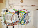
The top left white cable is the programmer,
The right cable is the Old stat which I need to disconnect.
The bottom left black powers the Grundfos pump
The bottom Right powers the motorised valve.

My wiring looks slightly different to that which appears to be online (S & Y) which is making it harder for me. Would you kindly guide me on where I need to move the cables to make the programmer work with the wireless Hive please?

Am I correct in thinking that the yellow currently at no 5 will need to move to no 3 (Heat on, on Hive)?
And what looks like grey coming from the black bottom right from the motorised valve will move from 10 to 3 also?
Still don't think that's right.....

Hopefully this makes sense! Thank you!


Picture1.png

Thermo.jpg
IMG-0523.JPG
 

Attachments

  • 20220826_065922.jpg
    20220826_065922.jpg
    403.4 KB · Views: 106
Easiest way to do it, fit the hive receiver where the existing Potterton is and wire as I already said, remove existing thermostat and join the two wires (red & Black) in a single terminal block and insulate , pop inthe wall and fit the hive thermostat over the existing hole , no need to touch anything inside the wiring centre, importantly before you do anything, on theexisting controller select only the heating and make sure the hw light doesnt come on with only ch selected, if it doesnt thats a fully pumped system if it does you have a gravity hw system, and will need to set the hive accordingly
 
Hi Ian,

Really appreciate the quick response.

Have just turned up the thermostat and put heating as 'on’ and the hot water did not come on along side it.

For absolute clarity, does that mean that I can install as per your instructions, remove the stat, cross the wires and leave the wiring centre alone?

Thanks!
 
Sorry, I also think the wires at the stat are blue and black - the red appears to be a jump. Does this make any difference?
 
As per your pic the wires are red & Black in terminals 1 & 3 of the room thermostat, the blue is not connected and is isolated, you need to join the red and black wires to complete the circuit, the Hive will take over this task,
Have just turned up the thermostat and put heating as 'on’ and the hot water did not come on along side it.

For absolute clarity, does that mean that I can install as per your instructions, remove the stat, cross the wires and leave the wiring centre alone?
Yes and set the Hive to fully pumped, should be set as that out of the box anyway
 
Back
Top