How to repressurise strange boiler?

Joined
23 Nov 2022
Messages
7
Reaction score
0
Country
United Kingdom
Hello, I have a Worcester Greenstar 25Si Combi MK IV boiler. Neither this model's manual nor all the Youtube tutorials on how to increase a boiler's pressure seem to correspond to what this boiler actually looks like: there is no slot for a filling link key, there is no keyless filling link blue lever, and I don't see an external filling loop anywhere.

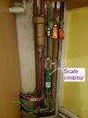
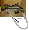
I may have found the place to attach an external filling loop that's below my sink, because it has 2 black taps, but I'm not sure. Does anybody know? I've attached pictures to show where in the boiler the pipes with the 2 taps are connected to (1 is marked green, the other pink).

Boiler underside: 1.jpg ⠀⠀⠀⠀⠀ Pipes continue down: 3.jpg ⠀⠀⠀ Then turn left below the sink with 2 taps: 4.jpg
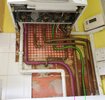
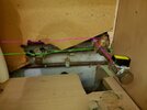
The boiler has symbols for each pipe that goes in, but nowhere in the manual nor internet can I find what they mean: they are a radiator, tap with arrow down, flame and tap with arrow up. I can't really tell which symbol belongs to which pipe because there are 5 pipes but only 4 symbols. Anyone know what the symbols represent?
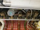
2.jpg

There is also a strange clear plastic container marked with a question mark; no idea what that does either.

Finally, directly below the sink there are some pipes but these are connected to the sink taps so I think they're irrelevant:
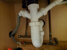
5.jpg

Any and all help would be appreciated; my boiler's pressure is at 0.4 bars (when warm): far below optimum pressure.
 
The plastic container will be the bottom of the condensate syphon. It can be opened to clean it.

The five connections, left to right, are:
- CH Flow
- DHW
- Gas inlet
- Water in
- CH Return

It doesn't look like you have an integral filling loop - I think it would bridge between Water In & CH Return (you can see the open ends where it would plug in), and there would be a plastic key to operate it.

I can't see how to fill it though. I think you're looking for a valve somewhere else that will add water into the CH loop from your mains supply - so that would be between the green pipe and either the purple pipe or the one on the far right (return path for the purple pipe).

Tempted to suggest - with the boiler turned off - giving each hand-adjustable valve a small tweak to see if any of them add water, starting with the plastic ones. Pic 3 just looks like a stop tap.
 
Last edited:
I would guess that the two valves with brass caps need to be connected by a filling loop. Do you have a braided hose somewhere? should be about a foot long. remove the brass caps and connect hose.
I would trace the pipes that the valves are connected to first to be sure. One should be mains cold water, the other should be heating system flow or return. Usually return.
 
Thank you, that explained a lot and the symbols make sense now.
giving each hand-adjustable valve a small tweak to see if any of them add water, starting with the plastic ones.
Which valves do you mean? The black plastic circles with screws that are by the symbols on the boiler? All 4 are plastic, so I'm not sure which other ones are there. I found another valve

And I think I shouldn't touch the Gas Inlet one (the middle connection, to the right of the condensate syphon): that one doesn't carry water obviously. I found another valve under the sink but it's on the gas pipe and leads outside so definitely shouldn't touch that one :mrgreen:

I would guess that the two valves with brass caps need to be connected by a filling loop. Do you have a braided hose somewhere? should be about a foot long. remove the brass caps and connect hose.
I would trace the pipes that the valves are connected to first to be sure. One should be mains cold water, the other should be heating system flow or return. Usually return.
I don't have a hose: I'll have to buy one. I'll try to trace the pipes... but eventually they go into the flat walls or deep behind the kitchen counter, how can I know their origin?
At least they correspond to the symbols by their temperature to the touch:
- CH Flow: Hot
- DHW: Hot
- Gas inlet: Neutral
- Water in: Very cold
- CH Return: Warm
 
Which valves do you mean? The black plastic circles with screws that are by the symbols on the boiler? All 4 are plastic, so I'm not sure which other ones are there. I found another valve

If there's a valve somewhere in the system, it would probably look a bit like the black plastic one in this pic:

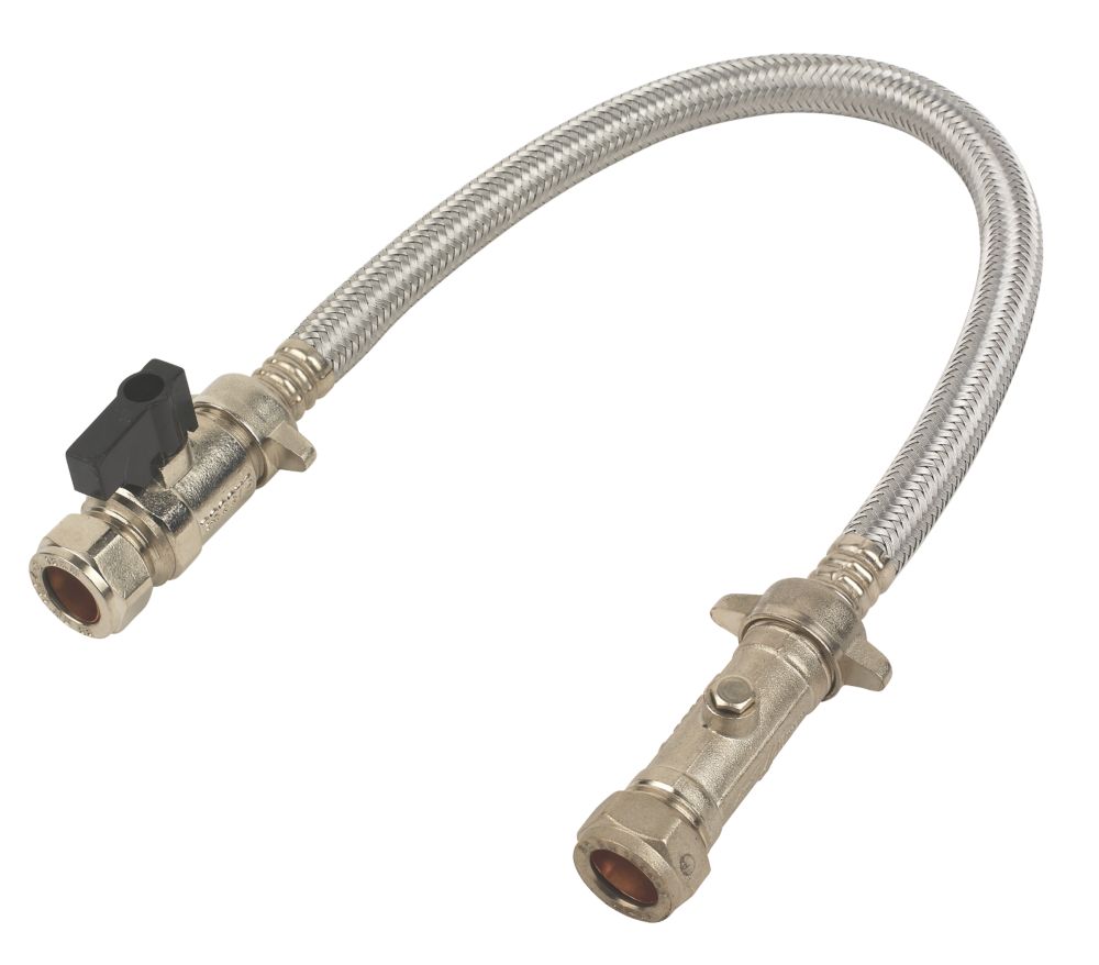
If you have a filling loop kicking around in a cupboard, it should look like the linked product. Edit: It should be connected between the pipes under the sink as you originally thought.

If you haven't had the boiler serviced this year, might be a good time to get that done and have them sort out a way to fill it at the same time.
 
Last edited:
Re ,The two pipes that you have coloured , are you certain that you have followed them from the boiler to under the sink ?
One of the valves under the sink ( left hand one ), doesn't look as though it's been used for years. How long have you lived in the premises ?
 
Re ,The two pipes that you have coloured , are you certain that you have followed them from the boiler to under the sink ?
One of the valves under the sink ( left hand one ), doesn't look as though it's been used for years. How long have you lived in the premises ?
Yes, I triple checked before, and now I checked again. The pink one connects to CH Flow on the boiler, the green one to the Water in. So that left hand valve is on the "Water in" pipe

I felt that valve and it wasn't stuck; maybe it's just grimy? Been living here off and on for over a decade, just never had the need to work on the boiler.
 
I did say it looked like it hadn't been used for years !!
Connecting the mains cold to the Ch flow will certainly top up the pressure .There should be a non return valve to protect from contaminating the mains ,ensure that one is fitted correctly on the loop that you use.
 
Sorry I just re-read your original post, @SpaghettiCat.

Yes, I concur with @Elkato531 and your original thought, the pipes under the sink look like where you would attach the filling loop I linked above. That'll be why you have those two valves in pic 4 - to allow you to unscrew the end caps without ****ing water all over the place.
 
OK, thank you very much everyone, I learnt so much about boilers!

To confirm, I'm going to unscrew the nuts on the valves under the sink (water won't gush out because the levers are in the closed position), then attach the hose such that water flows only from the Cold Mains to CH Flow, and open the levers on either end to permit flow.
 

Attachments

  • boiler_plan.jpg
    boiler_plan.jpg
    272.9 KB · Views: 75
You pretty much have it correct ,however you may need to introduce short lengths of copper pipe / olives/ nuts ,to enable the loop to be connected to the two valves.
 
get rid of that green scalemaster they split /pin hole and pish water out for fun
 
To give an update, the filling loop arrived yesterday, but valves cannot be connected to each other directly so I could not connect the filling loop to the valves under my sink. I have no idea why every filling loop comes with compression nuts: they do not help at all.

Then I had a stroke of genius: I unscrewed my shower head and used the hose from that to connect the valve to the filling loop.

After all this head scratching and research I've now understood the plumbing and boiler system of my house and have become a competent plumber, even replacing the 2 tight taps we had in the bathroom. Thank you all for your help :)
 
Looks like the loop you have has the compression connectors on but you don’t need them as you already have connectors fitted. You should have just removed the connectors and just used the loop.
 
Looks like the loop you have has the compression connectors on but you don’t need them as you already have connectors fitted. You should have just removed the connectors and just used the loop.
I could yes, but I needed to use the Non-Return Valve that came with the loop, otherwise boiler water may have flowed back and contaminated my mains.
 
Back
Top