Hybrid vent system

Joined
8 Jul 2024
Messages
5
Reaction score
0
Country
United Kingdom
Hello All,

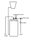
Just wanted to get some feedback on a system design I came up with.

I understand that in a vented system the water in the tank should remain below 20 degrees to prevent legionella but it never made sense why you would route the hot water vent pipe back into the tank. I took inspiration from unvented systems to avoid that flaw. My main concern would be the cylinder not being built to withstand 2-3 bar pressure (still trying to find a sub 2 bar prv) but I figured that actually any increase in pressure would just force water to expand back up the water inlet and any excess would go in the tank over flow. Does this design make sense or is it over engineered for something that isn't really a problem?


Another question I have is why do vented systems have a goose neck going over the top into the tank and not just have the pipe at a near 90degrees with a gentle rise? Wouldn't that help vent air better and avoid wasting extra length of pipe? Surely as long as the exit is above the water line and the over flow there shouldn't be any issues?


Thanks for any feedback,


Glnovice90
 

Attachments

  • hybrid vent system.png
    hybrid vent system.png
    6.8 KB · Views: 50
The pipe you are leaving out is a vent pipe ,why would it affect the temperature of the cold water tank any more than the design you have come up with.
 
I imagine just because it is used as a vent pipe doesn't mean it wouldn't be full of water. At the end of the day it is just another unrestricted outlet. What I'm trying to achieve is have the air escape through the automatic vent but in the case of thermal expansion under normal conditions or in the event of over heating, that all the hot water has a different path rather than getting dumped back into the tank and heating that up.
 
Your trying to solve something that isn't a problem.
The open vent will only discharge water back into tank if cylinder becomes overheated, Unless cylinder is heated by solid fuel it would need a failed thermostat to let water boil.
In normal operation any water expansion through heating takes place up the cold feed.
The other problem is auto air vents leak water for fun !
 
I understand that in a vented system the water in the tank should remain below 20 degrees to prevent legionella but it never made sense why you would route the hot water vent pipe back into the tank.

The vent pipe, only normally vents air, water doesn't normally flow up the vent pipe - why would it? The level in the vent pipe should never rise above the level in the CW cistern - the height of the pipe, rising above the cistern, ensures that.
 
Thanks for the replies. On the question of the vent pipe, I don't get the point of the 450mm rise above the CW level. As has been said on here there shouldn't be any water leaking out of the vent if its above the water level so why can't I get away with simply sloping the pipe into the side wall and saving all that copper.
 

Attachments

  • 450 rise.png
    450 rise.png
    21.7 KB · Views: 31
Thanks for the replies. On the question of the vent pipe, I don't get the point of the 450mm rise above the CW level. As has been said on here there shouldn't be any water leaking out of the vent if its above the water level so why can't I get away with simply sloping the pipe into the side wall and saving all that copper.

It's a vent pipe, air can vent up it, and the process of venting can take some hot water along with it, the 450mm prevents that. There will also be variations in localised pressure, when taps a turned on and off, again the 450mm, avoids those pressures forcing water out via that vent.
 
Thanks for the replies. On the question of the vent pipe, I don't get the point of the 450mm rise above the CW level. As has been said on here there shouldn't be any water leaking out of the vent if its above the water level so why can't I get away with simply sloping the pipe into the side wall and saving all that copper.
I think you're getting confused between the primary circuit (from the boiler through the cylinder coil) and the secondary (HW to the taps).
Your 1st pic shows the 2ndary. As you seem to be saying, the usual way is a vent pipe going up and over the CW tank. I suppose yours would work OK, but the only reason you'd need a PRV is if a valve in the cold feed to the cylinder is closed (and HW is called by the controls). And why 2.5 bar?

Your 2nd pic (the left hand part) shows a F/E tank on the primary circuit. That's where the 450 mm minimum is specified. There's a little headloss between the open vent and cold feed connections, which causes the level to rise slightly in the vent pipe. Should be much less than 450 mm, that figure gives some safety. I'm not aware of any minimum requirement for the loop over the CW tank, but maybe somebody is.
2.5 bar was the lowest I could find on bes.co.uk. I was hoping to find a variable prv and set it to the static head + margin but I'm going for the standard vent pipe anyway.

I assumed the CH and CW tank were both considered F&E tanks. Since they would both be reaching the same tempareture I didn't see why they would have different vent set ups. If anything, surely the CW is more of an F&E tank since you are always replensihing large volumes of water vs the CH tank which would be minor losses to evaporation and it wouldn't matter if the temp went over 20 as it's not potable water supply.
 
I assumed the CH and CW tank were both considered F&E tanks. Since they would both be reaching the same tempareture I didn't see why they would have different vent set ups.
The difference is the CH F&E tank is on a closed circuit and only tops up to replace evaporation and any leakage. There is a flow through the CWST whenever a hot or cold tap is opened. It doesn't have an expansion function.
If anything, surely the CW is more of an F&E tank since you are always replensihing large volumes of water vs the CH tank which would be minor losses to evaporation
As above, there is no flow through the CH F&E tank. I've explained the basis of the 450 mm expansion loop height on the F&E tank. Overpumping out of the vent pipe must be avoided, as it would bring loads of air into the circuit causing corrosion. Nothing similar can happen with the CWST as there is no pump.
The CH F&E tank is the more likely to see raised temperature, due to convection in the feed pipe. The feed pipe should enter the circuit up-and-under to minimise this.
 
Back
Top