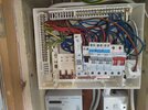
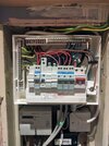
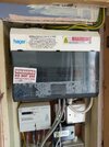
I converted my consumer unit to all RCBO, how did I do?

Joined
30 Mar 2023
Messages
28
Reaction score
1
Country
United Kingdom
Hey there!

A few weeks ago I posted on this forum asking for advice on converting my existing split-load Hager consumer unit to an all RCBO consumer unit.

Huge shoutout to the folks who provided some helpful feedback and shared their wisdom on competencies and qualifications. Your input was truly.. enlightening.

Now, I may not be an expert, but I did my best to follow the advice given by some genuinely helpful people who maintained a focus on the CU and complete the project. So, to all the wonderful people who contributed their two cents, I invite you to share your opinions on my handiwork. And to those who offered their, uh, "unique" perspectives on my abilities, I'm open to your feedback too - but please only if it comes with a side of constructive advice! ️

See a photo of the finished CU below.

JLE_20230418_194417_10Tp JOLE 84FS.jpg


JLE_20230328_172549_10Tp JOLE 84FS.jpgJLE_20230331_162429_10Tp JOLE 84FS.jpgJLE_20230418_200241_10Tp JOLE 84FS.jpgJLE_20230421_124758_10Tp JOLE 84FS.jpg
BeforeIn betweenAfterAfter (with cover)


Thanks again to everyone who helped!
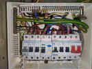
 
Looks OK, I did consider DIY route, but the cost of registering work was too high, however since not a new consumer unit, suppose it does not need it? I feel there is some thing wrong when we have to retain the plastic case or pay the LABC silly money.

In my case could not fit RCBO's in the old Wylex fuse box, so no option.
 
Why did you go down the RCBO route? Was it to prevent the RCB taking out all of the protected MCBs in the event of a leak to earth?

BTW, I am not an electrician. I am genuinely interested in your motives.
 
Why did you go down the RCBO route? Was it to prevent the RCB taking out all of the protected MCBs in the event of a leak to earth?

BTW, I am not an electrician. I am genuinely interested in your motives.
Couple of reasons, some better than others:
- No more space left in the unit while there are plans to add a circuit for an induction hob and eventually a car charger. Switching all MCBs out for RCBOs would give me an additional 2 spots since I'd be able to remove the RCCB. Ended up getting 3 since one of the circuits was not needed.
- I'm used to having all RCBOs in my consumer unit at my previous home (abroad). It's weird to me that lights would not be protected under an RCCB.
- I wanted to install a Shelly3EM in the consumer unit and got started on it before realising that the silly busbar design of my CU wouldn't allow me to fit it in there.
- I installed additional solar panels and wanted a type B RCBO for this.
- This seemed more feasible DIY than installing a new consumer unit since I don't have an isolator before the CU. Have heard of others fitting an isolator DIY with live voltage. I decided to give this option a pass.
 
Seem to remember about £350 but did not pay for labour, done as a favour, I had done enough for him in the past. Also fitted a SPD and external isolator.
Why did you go down the RCBO route?
For me, just before moving, the RCD tripped while not at home, and lost two freezers full of food, the cost of which was well above the difference between RCD route and RCBO route, and shortly after it had been fitted had a roof leak, so just as well.

One should really measure the leakage before fitting a RCD, but my clamp on went in 0.01 increments so can't actually measure the 0.009 amp considered as the maximum back ground leakage. OK have a meter now which will measure it, and also DC, but did not own that when changing the consumer unit those years ago.
 
I invite you to share your opinions on my handiwork. And to those who offered their, uh, "unique" perspectives on my abilities, I'm open to your feedback too - but please only if it comes with a side of constructive advice! ️

See a photo of the finished CU below.
So how constructive do you need advice to be?

How did you get round the issue of the bussbar not fitting?
 
Last edited:
You completely ignored the advice sticker on the Busbar cover, the main switch is still on.
 
So how constructive do you need advice to be?
Completely missed the email update about your reply!

I think a regular type of constructive will do, i.e. specific actionable suggestions aimed at improving a situation (taking constraints into account), while still being respectful and supportive.

How did you get round the issue of the bussbar not fitting?
It did fit before, but wasn't held in place correctly because of the BG breaker, which made it fit awfully crooked. I replaced the BG breaker and followed the advice from the previous thread to more or less use the same slots for the RCBOs as where the MCBs were. The plastic clips don't fit around the busbar, but based on the previous thread this doesn't have to be an issue as it is firmly held in place by the RCBOs. They are very brittle anyway and seemed to serve more as a guide for positioning the busbar correctly. It's not going anywhere unless multiple RCBOs are removed, which is only ever going to be done by someone who understands this CU.

I think it's a good compromise because the load isn't split over two busbars anymore, so it makes sense that the new busbar should have larger dimensions since it should be higher specced.
 
You completely ignored the advice sticker on the Busbar cover, the main switch is still on.
If you're referring to the "In between" photo, you're right. But that's an old photo which was already discussed in another thread linked.
 
Completely missed the email update about your reply!

I think a regular type of constructive will do, i.e. specific actionable suggestions aimed at improving a situation (taking constraints into account), while still being respectful and supportive.


It did fit before, but wasn't held in place correctly because of the BG breaker, which made it fit awfully crooked. I replaced the BG breaker and followed the advice from the previous thread to more or less use the same slots for the RCBOs as where the MCBs were. The plastic clips don't fit around the busbar, but based on the previous thread this doesn't have to be an issue as it is firmly held in place by the RCBOs. They are very brittle anyway and seemed to serve more as a guide for positioning the busbar correctly. It's not going anywhere unless multiple RCBOs are removed, which is only ever going to be done by someone who understands this CU.

I think it's a good compromise because the load isn't split over two busbars anymore, so it makes sense that the new busbar should have larger dimensions since it should be higher specced.
So correct me if I'm wrong but did I not offer one technical suggestion?

I suggested you obtained a copy of the Shelly MI as is contains some useful advice And even that you can't be bothered to do, instead you wrap plastic tape round it and produce this ****
1682679499873.png
and you wonder why I criticise?
 
Back
Top