Is my CH/HW fully pumped? Is it two-pipe?

Joined
19 Jun 2019
Messages
70
Reaction score
1
Country
United Kingdom
Hi,
I'm having problems understanding the exact configuration of the CH/HW piping in my house.
In particular, I have to understand where and how to place piping for additional radiators at the upper floor.

My configuration is the classical one: loft cistern, indirect cylinder on the upper floor, gas boiler on the ground floor. (my house is a two-floor terraced house, quite standard I'd say)
This is the official installation diagram taken from the boiler's installation guide (I think "heat exchanger" can be identified with "boiler" for our purposes):
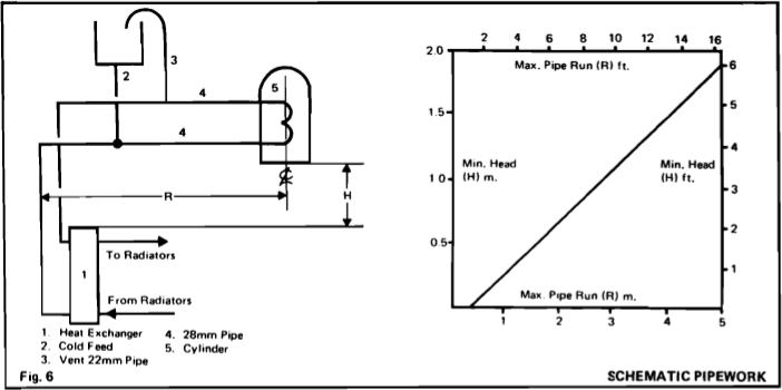
MEXICO-SLIMLINE2-CF40-CF50.png


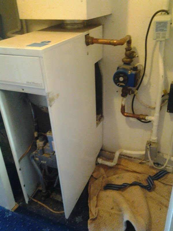
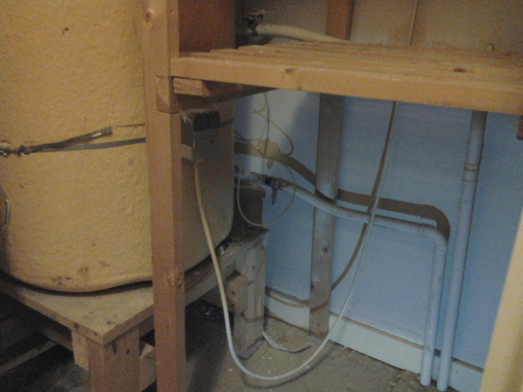
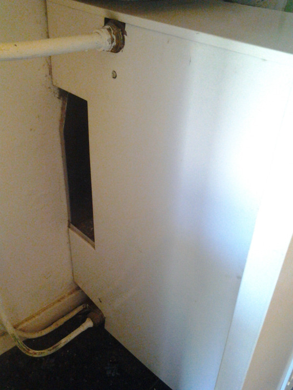
Contrasting that, this is how the boiler plumbing actually looks, from the left side (the smaller pipe on the bottom is irrelevant since it just passes through the boiler):
IMG-20190921-170802.jpg


and from the right-hand side:

IMG-20190921-170835.jpg


Given the number of pipes (4) attached to the boiler, and given the first figure, it looks like a non fully-pumped system.
However, the location and number of valves: one for HW (top right last picture) and one for CH (bottom right of last picture) suggests a fully-pumped one.

Any clue of what the actual situation is? Any test I could take myself to ascertain that?
And what about the radiators configuration? Is there a way to know if it's a two-pipe or one-pipe system?
As I mentioned, my main reason to know that is the perspective addition of radiators to the existing CH.

Thanks!
 
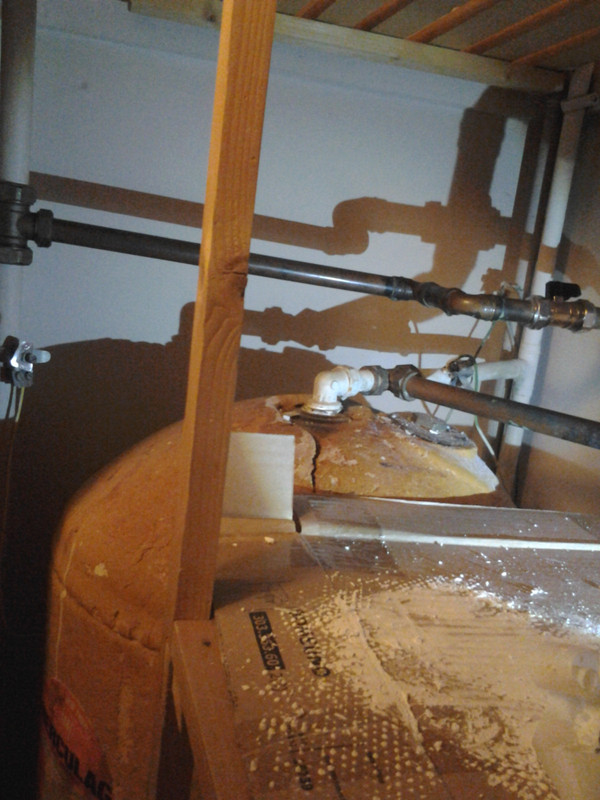
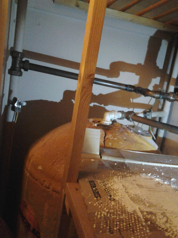
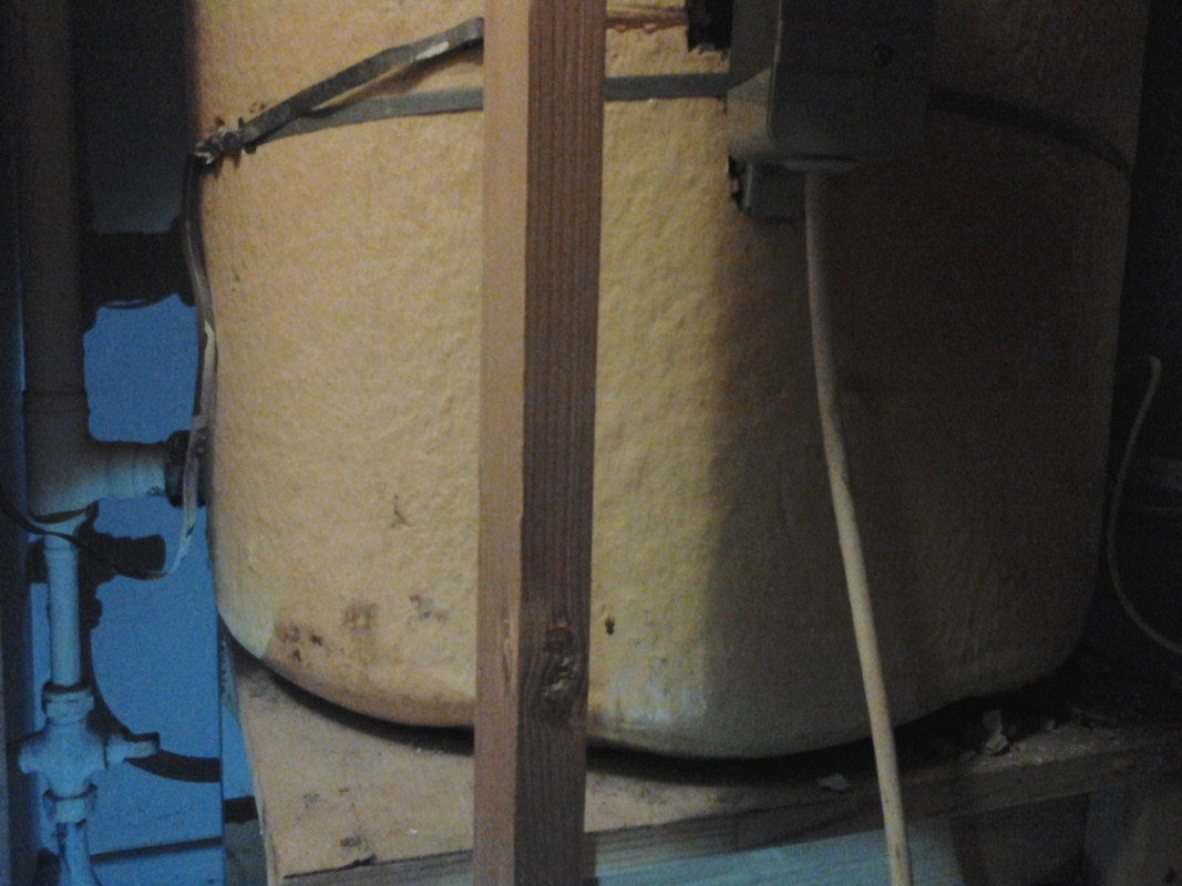
Difficult to tell, possible (and I seriously hope so), the left side are the HW Primaries, and the right side feeds the central heating. Possibly zoned for upstairs and down, but without seeing more of the system it's impossible to tell. What is the arrangement at the cylinder? Photo would be ideal, at least we can tell if you have a vent if nothing else!
 
From the limited information given... I would guess that it is an "s" plan with the vent and c/f exp taken from l/h side of boiler.
 
Difficult to tell, possible (and I seriously hope so), the left side are the HW Primaries, and the right side feeds the central heating. Possibly zoned for upstairs and down, but without seeing more of the system it's impossible to tell. What is the arrangement at the cylinder? Photo would be ideal, at least we can tell if you have a vent if nothing else!
cylTop00.jpg


cylTop01.jpg


cyl-Bottom00.jpg


cyl-Bottom01.jpg


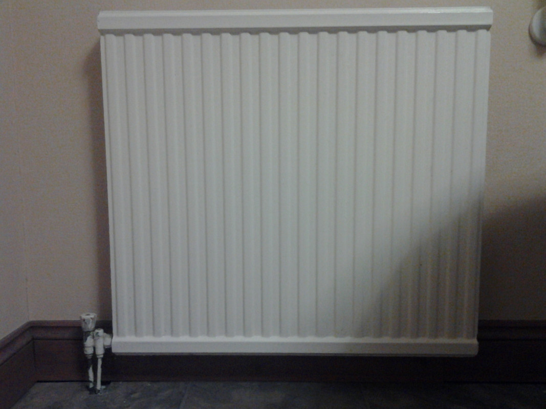
I also attach a picture of a radiator, maybe this can help wrt the 2-pipe vs 1-pipe CH question:

rad.jpg


Thanks in advance!
Cheers
 
Another thing I forgot to tell, wrt to the boiler pictures in the first post.
I tested the system with HW and CH both on, and all rads hot: both pipes connected to the right of the boiler are definitely hot, while both pipes on its left are definitely cold (possibly, the bottom-left pipe is even colder than the top-left one?).
Looks like the system has NOT been installed as from the very first figure of this post, but the main question about 2-pipe vs 1-pipe CH remains.
 
System looks to be fully pumped, but possible you have 'Microbore' central heating, whereby all the rads are fed individually from a central manifold in small bore pipework. Are all the radiators connected in a similar vein?

Pipework from L/H side of the boiler may well be the Vent and feed, have to wonder if it's an old Gravity HW/Pumped CH system that's been converted to fully pumped.
 
System looks to be fully pumped, but possible you have 'Microbore' central heating, whereby all the rads are fed individually from a central manifold in small bore pipework.
Yes, this makes sense. I measured the outer diameter of the pipes feeding the radiator in pic above. It is 8mm, I think. I don't like that.
I have a question: would micro-bore imply a two-pipe CH, or can you also find one-pipe micro-bore systems? I cannot figure out how the latter would be possible, but I'm asking because that could help settle my questions.

Are all the radiators connected in a similar vein?
Most, but two of them look a bit different.
One has a larger pipe with an additional adjustable valve. I think the larger pipe is the output one, since it was colder upon testing:
larger-Rad.jpg


A second one has the usual smaller pipes, but again with an additional adjustable valve on the output:

smaller-Rad.jpg


Pipework from L/H side of the boiler may well be the Vent and feed, have to wonder if it's an old Gravity HW/Pumped CH system that's been converted to fully pumped.

This is quite possible, even more so because I realised that the configuration in the very first picture is not the only possible one.
Indeed, the boiler manual says:

The appliance must NOT be used for direct hot water supply or for sealed system.
The following indirect open vented systems are suitable:
Combined gravity domestic hot water and pumped central heating.
Combined pumped gravity domestic hot water and pumped central heating.
Pumped central heating only.
Gravity domestic hot water only, up to a minimum domestic hot water cylinder storage capacity of 180 litres (40gal.).

Sorry for missing that in the first place!
I conclude with another quote from the boiler installation manual possibly relevant.
If anyone manages to draw further possible conclusions about my system, please feel free to write them!
Thanks!

The flow and return connections to a fully pumped system may be made
either at one side of the boiler or diagonally to suit convenience.
In a combined pumped heating and gravity domestic hot water system, the gravity flow
and return connections must be made to the same side of the boiler, and the
pumped connections to the opposite side. The boiler must be vented.
 
If it is microbore then definitely 2 pipe.

The other rad is only piped T B S E for wall space.
 
If it is microbore then definitely 2 pipe.

The other rad is only piped T B S E for wall space.

Great, this thread's been very helpful, thank you to everyone.
Another thing I find strange is that I don't see a relief (automatic bypass) valve in the third picture.
I understand it should link the two pipes attached to the boiler in that picture before the tee.
Am I right?
 
Not every system has a bypass, but if you have a Radiator with 2 Lockshield valves on it, (often the Bathroom Rad), then the valves can be left open at both ends to act as a bypass, or alternative a manual bypass, (with a gate valve), can be fitted somewhere on the system.
 
Not every system has a bypass, but if you have a Radiator with 2 Lockshield valves on it, (often the Bathroom Rad), then the valves can be left open at both ends to act as a bypass, or alternative a manual bypass, (with a gate valve), can be fitted somewhere on the system.

But in this way you only relief the CH, I think.
What if the CH valve is shut and you need to relief the HW? Or am I missing something?
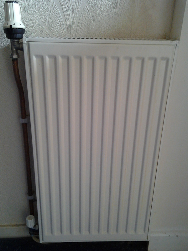
Another question, sorry (I'm learning a lot:): what are the names of the radiator valves in the last picture? Is the one on the right a TRV? What's the name of the other one?
 
You have what appears to be a 'S' plan system, with Separate valves. If HW is calling for heat, then the HW valve must be open, providing a path for the water from the boiler. With CH, it is possible the room stat may still be calling for heat, but individual Rads with Thermostatic Radiator Valves (TRV's), are shutting down, thus restricting the path for the flow from the boiler. To prevent system damage, the bypass would allow a path for that flow.

As to the pic, yes, Right valve is a TRV, left is a standard rad valve. If TRV's aren't fitted then a standard valve is fitted at either end of the rad. Normally one end would be fitted with a wheelhead, (as in the pic), which allow the valve to be closed off if the rad isn't needed. The opposite end would have a 'Lockshield' cap fitted, Basically a protective plastic cap that doesn't alter the valve position is moved. The Lockshield should be set by the installer to 'Balance' the system, basically a procedure to ensure all the radiators get the required flow of water from the boiler to ensure even heating across the property.
 
You have what appears to be a 'S' plan system, with Separate valves. If HW is calling for heat, then the HW valve must be open, providing a path for the water from the boiler. With CH, it is possible the room stat may still be calling for heat, but individual Rads with Thermostatic Radiator Valves (TRV's), are shutting down, thus restricting the path for the flow from the boiler. To prevent system damage, the bypass would allow a path for that flow.

Ok, got it, thanks. I was being overly paranoid, thinking about scenarios when the HW valve is stuck or closed for some reason and the boiler pumping hot water nevertheless, for some reason.

As to the pic, yes, Right valve is a TRV, left is a standard rad valve. If TRV's aren't fitted then a standard valve is fitted at either end of the rad. Normally one end would be fitted with a wheelhead, (as in the pic), which allow the valve to be closed off if the rad isn't needed. The opposite end would have a 'Lockshield' cap fitted, Basically a protective plastic cap that doesn't alter the valve position is moved. The Lockshield should be set by the installer to 'Balance' the system, basically a procedure to ensure all the radiators get the required flow of water from the boiler to ensure even heating across the property.

Which brings me to another question (sorry, if I ask too many, just ignore me :) ): do TRVs for one-pipe systems exist? Are they different than ones for two-pipe systems?
 
TRV's are standard, they're quite simple in operation, simply adjusting the opening of the valve to regulate the flow into the room according to ambient temperature of the surrounding air, with One pipe systems relying on convection and gravity somewhat more than a Two pipe system, I'd have to question the need or effectiveness of using TRV's on such a system.

One Pipe systems were usually larger bore pipework, I recall moving a cast iron radiator in a large Victorian Property as an apprentice. I was left chopping out the floor for the pipe runs to the new rad position as the Plumber had to travel the 20 miles to Northampton to get the large copper fittings we required to make the alterations. From memory the pipework was 1 1/2" or possibly bigger, we reduced it down to 22mm to feed the rad.
 
TRV's are standard, they're quite simple in operation, simply adjusting the opening of the valve to regulate the flow into the room according to ambient temperature of the surrounding air, with One pipe systems relying on convection and gravity somewhat more than a Two pipe system, I'd have to question the need or effectiveness of using TRV's on such a system.

Maybe TRV's on the first radiator would change the behaviour of those on the farther rads?

One Pipe systems were usually larger bore pipework, I recall moving a cast iron radiator in a large Victorian Property as an apprentice. I was left chopping out the floor for the pipe runs to the new rad position as the Plumber had to travel the 20 miles to Northampton to get the large copper fittings we required to make the alterations. From memory the pipework was 1 1/2" or possibly bigger, we reduced it down to 22mm to feed the rad.

I tend to like those old big radiators :)
Was it a steam-based one?
 
Back
Top