Hi all,
First time contributer here… Hope all well and apologies if my questions are stupid…! However:
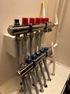
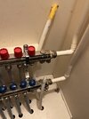
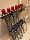
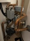
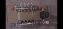
I’m trying to get my head around my UFH installation - I moved into my house about a year ago (the house itself is about 14 years old) and I’ve never quite understood the UFH system/been able to get a consistent outcome. I also wonder whether it is correctly installed or not…? I attach a couple of photos which may help to explain, but I guess the crux of my questions are as follows:
- the hot water feed is attached to the blue headed part of the manifold, which seems counter-intuitive to me? Is that the correct way or…?
- also, the adjustable flow valves are at the bottom, under the blue headers (I’ve unscrewed one to show…)
- I don’t have any flow meters - can I add them? If so, would they go at the top or bottom?
- there is a random pipe, which seems to be of a different type to the others, which isn’t connected to the manifold and I don’t know where it “flows” to. Any thought on why it’s there/not connected/why it seems to be different to the others?
FYI, UFH is for downstairs only whereas upstairs is traditional rads with thermostatic valves.
The UFH pump is upstairs near the water cylinder and seem to be working fine.
Many thanks in advance for any comments/guidance!


