- Joined
- 13 Oct 2023
- Messages
- 10
- Reaction score
- 1
- Country

I'm hoping someone can help me with this wiring.
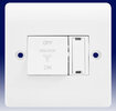
I have fitted an extractor fan that has humidity & override. I've created a spur from a ring main with 2.5 T&E cabling, to a fused spur with 3a fuse (crabtree 4827). I was told I must do this as I've tapped off the ring main. From the spur I've used 3&E cabling. The 3&E then feeds from the sur to the fan kill switch (crabtree cr1008), then into a switch for the switched live, so that I can switch the fan on or off (crabtree cr1014) when I want. The permanent live & neutral cables bypass this switch with the aid of two wago connectors. The 3&E then feeds into the fan.
Everything works fine & dandy, the fan comes on when it detects too much humidity & runs for about 15 minutes & I can turn it on & off when I need it with the switch (crabtree cr1014).
There is however one issue. The on/off switch (cr1014) has an intergrated LED as I wanted a visual reminder that I'd actually switched it on & then know that I need to switch it off. So the switch works as an on/off switch to power the fan OK, but the integrated LED (in the switch) doesn't come on as the neutral cable bypasses the switch as it is needed for use with the permanent live.
Not wanting to mess with the wiring & do anything dangerous I've left it in this position, but I'd really like the LED to come on when I turn that switch on.
So can I create & add a loop from the existing neutral cable at the wago connector to go through the neutral terminals in the switch? To me this seems logical as the existing neutral will work with the permanent live & also the switched live, in so far as when the switch is in the off position, the flow will go through the cable in its current configuration, but with the switch on, it will also go through the switch, thereby powering up that LED.
Or do I need to do something completely different? Obviously I'm not an electrician, so if anyone has a solution that works, please let me know.

