LED TV with no power light (but circuits showing voltage)

Joined
3 Aug 2016
Messages
48
Reaction score
1
Country
United Kingdom
Hi all,

I have a TV that stopped working randomly one day (not powering on and no power light). I have performed the following troubleshooting steps before opening the TV:

1. Checked fuse of power cord
2. Tried another power cord
3. Changed batteries in remote
4. Pressing power button located under the TV

I then proceeded to open the back panel and tested the continuity of the fuse that was on the power board (which seemed fine). I then carefully used an electrical tester to see if the power was flowing from the power board to the AV board (where all the HCMI etc. connections are) and I could see that there was 12V live power there. I could see power readings on the metal surfaces around the TV as well (neutral?).

I know that the LED strips could be an issue, but before I go tearing the TV apart, is it possible to get some help on what to check and how to check? I have an electrical tester and a multimeter. I have uploaded some pictures that may be of relevance. Happy to put up more images or zoom into any specific area as required.

TV is a HiSense 50A7GTUK (couldn't find a service manual online)

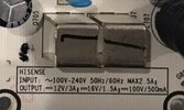
IMG_6267.jpeg


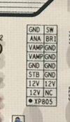
IMG_6268.jpeg


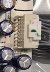
IMG_6269.jpeg
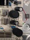
IMG_6270.jpeg
 
used an electrical tester to see if the power was flowing from the power board to the AV board (where all the HCMI etc. connections are) and I could see that there was 12V live power there.
What exactly have you used, and where was this 12V?

No power light at all suggests the power supply has failed, which is the white board on the left.
It has several voltage rails, there appears to be a diagram near the centre of the board.
A large photo of that board only so that the components and markings can be seen would be useful.

Thanks for getting back. I am using a Digital Voltage Tester by Rolson

61cCoXa3BcL._AC_SL1500_.jpg


I also have a multimeter :
IMG_6296.jpeg


I tested the topmost pin where the ribbon cable from the power board plugs into the AV board. I got a reading of 36V when I put my thumb on the Induction Breakpoint Test point, and a reading 55V on the Direct Test point.

IMG_6298.jpeg


I also tested at one of the screws on a board which I think may be for the picture, and it was showing a reading of 36V and 55V as well.

Close ups of the power board are below:
IMG_6291.jpeg

IMG_6292.jpeg

IMG_6293.jpeg

IMG_6294.jpeg

IMG_6295.jpeg
 
Last edited:
I think may be for the picture, and it was showing a reading of 36V and 55V as well.
I'm afraid your measurements dont make much sense to me! You need to use your multimeter.
The outputs from the PSU board are listed as 12V, 16V and 100V here:
Screenshot_20221211-220258_Chrome.jpg
The outputs from the ribbon cable would be a good place to start:
Screenshot_20221211-220023_Chrome.jpgScreenshot_20221211-220031_Chrome.jpg
This connector may be the 100V for the backlight:
Screenshot_20221211-220100_Chrome.jpg
(Although unlikely to be powered if in stand by)

....but, it may be just as easy to replace the whole board, example here:
 
Check the 12V first, as without that, nothing will work.
Multimeter set to volts, black probe on the top pin of the connector (GND), red one on the lower pin (12V).

Note that everything on the left side of the board (HOT) will be at 240V when power is connected.
 
I'm afraid your measurements dont make much sense to me! You need to use your multimeter.
The outputs from the PSU board are listed as 12V, 16V and 100V here:
View attachment 288689
The outputs from the ribbon cable would be a good place to start:
View attachment 288691View attachment 288690
This connector may be the 100V for the backlight:
View attachment 288692
(Although unlikely to be powered if in stand by)

....but, it may be just as easy to replace the whole board, example here:
Thank you, I did see a hint of 110V on the digital dester, and now it makes sense why.

I have looked at that link and it seems like that would be the way to go if it's too much trouble to identify the fault.

Check the 12V first, as without that, nothing will work.
Multimeter set to volts, black probe on the top pin of the connector (GND), red one on the lower pin (12V).

Note that everything on the left side of the board (HOT) will be at 240V when power is connected.

Thank you for clarifying where to check, I was a little lost for a moment there when I looked at @RandomGrinch's helpful response on my phone (wasn't sure how to check the pins). I checked the pins as you both suggested and it seems that there is no voltage reading between the first and last (and second to last) pins. So I guess the issue lies in the power board.

Would it be worth trying to work through the powerboard to identify and resolve the fault before splashing out on a power board and hoping that there are no other issues?
 
Would it be worth trying to work through the powerboard to identify and resolve the fault
Only if you know how these things work and have the capability to test and replace individual components.

The power supply board is available from several places including ebay, replacement is by far the easiest option.
 
Only if you know how these things work and have the capability to test and replace individual components.

The power supply board is available from several places including ebay, replacement is by far the easiest option.

Thank you for the advice, I have found one on eBay as suggested. I will go with that and hope nothing else is wrong :)

Thank you and @RandomGrinch for the quick replies
 
Pleased to report back that the power board swap worked and tv is back to life with no other apparent issues! Thank you for the help :)
 
Back
Top