Muting external sounder on i-on40H

Joined
4 Jun 2017
Messages
11
Reaction score
1
Country
United Kingdom
Hi. Does anyone know if it's possible to mute an external sounder on an i-on40H? It's a new installation which I did myself and I want to get familiar with it without annoying the neighbours. I know that I can disconnect the Bell Trigger wire in the panel but would prefer not to do it that way. Thanks.
 
Appreciated but if power goes off it auto reverts to 15 mins

do you know this system Mark?

because I’m having a mare with the wired PIR

there just not working

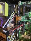
pics attached how I was told to wire

your thoughts much appreciated

best Neil
 

Attachments

  • F88272DE-648C-44FF-9FFE-864D9224AF40.jpeg
    F88272DE-648C-44FF-9FFE-864D9224AF40.jpeg
    173.4 KB · Views: 57
  • 13BA34A2-28F1-4D8B-9962-532C01E5B54F.jpeg
    13BA34A2-28F1-4D8B-9962-532C01E5B54F.jpeg
    424 KB · Views: 70
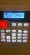
Am using 2k/4k resisters so selected

(FSL) 2 cable 2k/4K7 as my setting

Other options are 2cc or 4cc 2 wire in either

1k/1k
2k-2k
2-4k
4k-4

turned on Masking tonight and 3 out of 6 now showing a resistance on the keypad


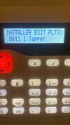
And just as it was getting better, now I have a Bell Tamper fault, which I didn’t have before

Aaarrgghhhhh

does that all look right.?

must have a wire pinched on the sleve somewhere, a# been over PIR with a fine toothcomb, so willl look closely at panel to row. Unless you have any other ideas.

ty Neil
 

Attachments

  • AB9DEA9D-5ACB-48C2-B7B6-BC48FC373A7F.jpeg
    AB9DEA9D-5ACB-48C2-B7B6-BC48FC373A7F.jpeg
    153.8 KB · Views: 46
  • 44F477AA-37EB-4022-8516-EC85776D8BEC.jpeg
    44F477AA-37EB-4022-8516-EC85776D8BEC.jpeg
    164.3 KB · Views: 47
Is this a self install.
New bell tamper would suggest tamper switch not adjusted correctly or wiring fault.Due to the recent hot weather is the bell box in sunny position as heat can affect the covers.
I would suggest make all zones not used,then turn one zone on and concentrate on that zone until system works correctly. Then you can move onto next zone.This way you prove that zone programming is correct on each zone.
Your wiring does look correct which points to programming.
 
it wasn’t originally, I installed all the Radio PIR they are nice and easy and switched the panel and keypad over then had a professional wire it but the transformer blew on the panel and they switched the whole thing over, which I did by just mirror imaging what was there but the previous guy didn’t use resisters anywhere and was wired in a way that no one said was right……hence maybe it blew but getting someone who knows this system locally proved a tall order…..

so been learning on my feet and started again but back to the same point, where all radio PIR all good ✅

wired ones having some issues, plus the wiring on all PIR was different, so had red on one for 12v then Red for T1 then red for C nightmare

somswitched them all over to

red 12v
black 0v
yellow T1
Blue C

So thinking I have those right now

the other issue is 2 door sensors magnetic, you only use the yellow blue for that correct to z1 z2 at panel, however they both have 4 wires wired in red black yellow blue…… you ignore the red black correct?

but at panel join them in with a PIR so they are

yellow z1 PIR
blue/yellow C PIR and Mag DoorSwitch
blue Z2. Mag door switch

ignore red black for Switch and put red black PIR to Aux 12 v/0v

using no resisters on Switch? Is that correct?

then issue 2 they have spured 2 PIR sensors off each other, so you just use the one cable, wired as above.

Do both PIR have to be wired with resistors or just one? And is that wired any different at panel?

Yes box is in direct sun, wasnt having any issue with that and now that’s my only fault to leave installer menu but will check over wiring at Panel, as I haven’t been anywhere near the alarm box outside.

2 switches
2 linked PIR
3 PIR These all now showing resistance on keypad now so that’s halfway ✅

THANK you all for your input

Much appreciated
 
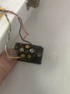
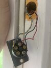
Can you post photo of door contact and wiring.
Can you post better photo of zone wiring inputs on pcb.
All zones 1-8 will be FSL (Eol)
Any un used zones need programming not used and I would put 2.2k in spare zones to eliminate and programming issues.
Door contacts will require resistors.
As I said start with one zone get that right then move on to next.
Put link wire in Tr(tamper return) and 0v to clear tamper fault,then investigate once sorted other issues.
Once you have a clear panel will make it a lot easier to move forward.
 
switch wiring front door

2nd photo

Switc wiring rear door
 

Attachments

  • AB7CDFF9-3AB0-4191-8A94-C2289DCC8DE3.jpeg
    AB7CDFF9-3AB0-4191-8A94-C2289DCC8DE3.jpeg
    187.5 KB · Views: 60
  • 6CE909D2-2380-4D57-99C3-04D331DD75FA.jpeg
    6CE909D2-2380-4D57-99C3-04D331DD75FA.jpeg
    218.7 KB · Views: 53
The contact in your picture above is 4 wire.
red and black is the alarm pair and blue and yellow the tamper pair.

I can see from the manual, that the panel and older expanders require you to use the same wiring methods throughout.

so any sensor wired to the panel must use the same wiring type ie resistors if that is what you have selected.
If you have an expander you would have to check if you have the expander that is capable iof accepting mixed wiring types.
 
Last edited:
Ok added resistors and had lost the bell tamper and had front door contact and hall pir working Horrah ….

wired the rest the same and to my utter disappointment a totally new issue, where the keypad now isn’t reading the panel

tried turning system off powe down etc back up but just come back to as if it’s a new keypad with

Eaton V5.1
time 00:00 date 14/04/2001

tried holding down A✅ To get Panel address and just beeps about 10 times and has adr ————-

Eaton said try power down back up holding D X reset but doesn’t help and panel is non responsive except if you hold B✅ Gets you into the backlighting menu but once out back to Eaton V,5 etc

this is all done with the keypad away from the wall.

god this is frustrating!

though you had all helped me crack it then…
 
Back
Top