Nest (s) wiring sanity check - multi zone replacement

Joined
14 Jan 2009
Messages
64
Reaction score
2
Location
Oxfordshire
Country
United Kingdom
Hi all,

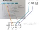
Looking to replace a 2x zone CH programmer and HW controller with 2x nest.

Nest 1- (3rd gen) will control downstairs heating and HW
Nest 2 - (nest “e” thermostat) will control upstairs heating.

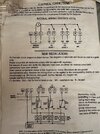
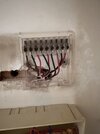
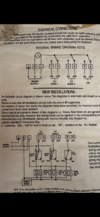
Current programmer has seemingly simple wire structure, a series of neutral and live each channel for on and off.

Can someone confirm, if I was to use this same wiring to connect to both heat links I would connect as follows:

3rd gen Heat link:
N- N
L - L, bridged to 2 and 5.

1 = current “2” - heating off
2 - bridge
3 - current 1- heating call

4 = Current 6 - HW off
5 - bridge
6 - current 5, HW call


Thermostat- e heatlink
C = current 3 - heating call
NO (normally open) = current 4 - heating off
Note thermostat e heat link appears to be battery powered.

Can someone confirm if i have this right or not?

Thanks :)
 

Attachments

  • IMG_5733.jpeg
    IMG_5733.jpeg
    385.8 KB · Views: 74
  • nests.jpeg
    nests.jpeg
    271.3 KB · Views: 58
  • IMG_5737.jpeg
    IMG_5737.jpeg
    239.1 KB · Views: 59
Last edited:
The normal for your system would be 3 x 2 port zone valves then HW off and CH off are not used, better to post pics of what you have makes it easier to advise
 
The normal for your system would be 3 x 2 port zone valves then HW off and CH off are not used, better to post pics of what you have makes it easier to advise
No problem, picture uploaded to original post thanks :)

All connectors are used on the original programmer
 

Attachments

  • IMG_5731.jpeg
    IMG_5731.jpeg
    219.2 KB · Views: 68
  • IMG_5735.png
    IMG_5735.png
    1.5 MB · Views: 64
origional wiring was wrong then, HW off is only used if you have a mid position valve (3 port) and CH off is very seldom used unless you have air con or similar
Very odd mate, all on’s and off’s have wires in them - maybe for show? Also @Grangey the Earth isn’t sleeved. Very odd and wrong wiring as @ianmcd states
 
Very odd mate, all on’s and off’s have wires in them - maybe for show? Also @Grangey the Earth isn’t sleeved. Very odd and wrong wiring as @ianmcd states
So should I trace where the wires are going to? Gotta be doing something to bother wiring surely… Current programmer works fine so somethings strange for sure
 
So should I trace where the wires are going to? Gotta be doing something to bother wiring surely… Current programmer works fine so somethings strange for sure
Maybe they’re in a connector block in the wiring center - certainly worth tracing.
 
So should I trace where the wires are going to? Gotta be doing something to bother wiring surely… Current programmer works fine so somethings strange for sure
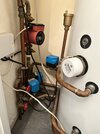
Ok wiring centre is spaghetti junction with some connections hard to see, so I’ve traced one valve visually as best I can (the closest lower value seen in the picture) which is the downstairs zone.

Valve has 4 wires
Blue, brown, orange, orange grey.
These feed to a connection block that maps to
Blue - Blue
Brown - Black
Orange - Red
Grey - Yellow

B/B/R/Y then go to a second location where

Blue seems to go to another connection block all leading to other and splitting other Blues, so believe this is neutral.

Black appears to go up to the current programmer

Red goes into a bridged series of connections that also appears to end up being the red going to the programmer.

Yellow goes to a red connection that’s bridged a number of times with with other cables in variety of colours before in general, traceable to a red that potentially links to the boiler.
 
Last edited:
Afraid that wires in a heating system mean absolutely nothing, the only colours you can rely on are the factory fitted flex to the zone valves, they are normally correct, anything connected to them can be any colour, welcome to our world we have to navigate this stuff every day
 
Afraid that wires in a heating system mean absolutely nothing, the only colours you can rely on are the factory fitted flex to the zone valves, they are normally correct, anything connected to them can be any colour, welcome to our world we have to navigate this stuff every day
Understood but based on the above tracing does that not help determine what the cables in the “off” position are for?
 
Understood but based on the above tracing does that not help determine what the cables in the “off” position are for?
Sorry I have no clue where the "OFF" position wires go as they are not used on your system, on all valves , the orange wires from the valves should all be in the same terminal, all the grey wires should all be in the same terminal, all the blue wires should all be in the same terminal, all earths if present should all be in the same terminal ( I must stress these coulours are ONLY for the factory fitted flexis from the zone valves) everything else is a lottery, then the Brown for each individual zone valve is where the controls wire to, the controls wire to the zone valve , when the valve opens the valve tells the boiler and pump to come on
 
Sorry I have no clue where the "OFF" position wires go as they are not used on your system, on all valves , the orange wires from the valves should all be in the same terminal, all the grey wires should all be in the same terminal, all the blue wires should all be in the same terminal, all earths if present should all be in the same terminal ( I must stress these coulours are ONLY for the factory fitted flexis from the zone valves) everything else is a lottery, then the Brown for each individual zone valve is where the controls wire to, the controls wire to the zone valve , when the valve opens the valve tells the boiler and pump to come on
If I understand you correctly, are you saying that if this was a freshly installed system, the only terminals populated in the 3rd gen heatlink (excl L and N), are ports 3 and 6?
 
Ok after a lot of reading I’m certainly considering redoing the entire wiring centre to make sense of what’s what and harmonise the colours.

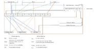
Can someone confirm if this looks correct bar the missing link from the pump to the boiler?

The only part I’m stuck on is how the CH valve says it should go to both the boiler and pump, but the HW valve only the boiler.. surely by wiring to one you’re wiring to both?
 

Attachments

  • image001.png
    image001.png
    56.6 KB · Views: 42
Very odd mate, all on’s and off’s have wires in them - maybe for show? Also @Grangey the Earth isn’t sleeved. Very odd and wrong wiring as @ianmcd states
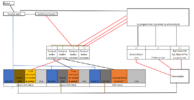
Ok I’ve traced it visually and am left with the following:

Blacks to the programmer are all Neutrals.

The 3 reds that go to the programmer, are the 3 valve “live on boiler and/or pump” but the wiring here confuses me:

There are 4 terminals all bridged/ linked.
1: has just the “live termial for boiler” from zone 2
2: has the “live terminal of pump and boiler” from zone 1 and HW valves.
3: has the live from an unfused switch - that appears to do nothing, and one of the reds that go up to the programmer
4: has 2 reds that go into the wall and by process of elimination believe to be the remaining 2 reds that go to the programmer.

The boiler and pump share a live, but not a neutral.
The boilers neutral heads to a terminal block which:
-Connects to the unfused switch
- provides 1 of the 4 blacks that head up to the programmer
- and goes to the same shared neutral connection the pump and zone 1 valve share.

Here’s a heavily omitted visual with a sample of the mixed colours at play:
 

Attachments

  • image001.png
    image001.png
    40.9 KB · Views: 39
Last edited:
Are you sure they’re all neutrals? Seems odd, as when switched off they would become live
 
Back
Top