- Joined
- 16 Oct 2023
- Messages
- 8
- Reaction score
- 5
- Country

Help with dual zone wiring - Nest thermostat UK
Hi, I am following a diagram and installing the heatlink to the wiring centre. Seems all should be correct but it puzzles me that the brown wire of the danfoss HPA valves are going into the black wire of the thermostat but on my thermostats this is going into COM not NO.
At moment the plan is:
1. Blue neutral from Valve to Neutral in heatlink
2. Grey Live from Valve to Live in heatlink - remove the stats wires to use on T1
3. Orange from Valves leave as is to boiler only
4. Brown from Valves each to a corresponding terminal 3 (NO) in heatlink - remove the stat wires to use on T2.
5. Also bridging L to 2 in heatlink
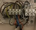
The wires coming from the very bottom in the wiring centre picture are from the valves, there are also 2 loose neutrals from the stats as they were not needed. On the left are the boiler wires, the stats wires are the ones coming from the wall on bottom right.
Maybe I am overthinking but I don’t understand why the black wire from the stat is going into COM? Voltage measured on NO is 230v whilst 12V on COM on the stats…
The connectors have been also installed to plate upside down and do not match the labels but I figured based on the valves wiring.
I hope this makes sense to someone who is able to help.


