Nest wiring - ideal logic combi ESP1 35

Joined
5 Oct 2022
Messages
2
Reaction score
0
Country
United Kingdom
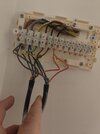
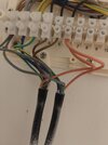
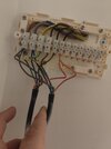
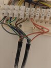
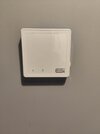
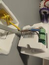
Hello everyone, I am looking to change my naff ESI thermostats to Nest gen 3's and wondered if someone could help me with the wiring. I have two motorised valves in the upstairs airing cupboard along with the wiring centre. I've checked the back of the facia on the wiring centre and there isn't any information regarding which wire is which. In terms of the set up, I've got an ideal logic ESP1 35 combi with two Thermostats controling each floor of the house. Ideally I'd like to just reuse the existing thermostat wiring for the nests. I've attached pictures of the wiring centre for reference but any help would be gratefully received
 

Attachments

  • IMG20221005083117.jpg
    IMG20221005083117.jpg
    160.5 KB · Views: 279
  • IMG20221005083122.jpg
    IMG20221005083122.jpg
    179.6 KB · Views: 273
  • IMG20221005083117.jpg
    IMG20221005083117.jpg
    160.5 KB · Views: 254
  • IMG20221005083122.jpg
    IMG20221005083122.jpg
    179.6 KB · Views: 235
  • IMG20221005084754.jpg
    IMG20221005084754.jpg
    158.7 KB · Views: 248
  • IMG20221005084930.jpg
    IMG20221005084930.jpg
    180.5 KB · Views: 284
You move the wires from the ESI to the terminals of the Heat Link that have exactly the same function. So:

Brown wire in - ESI 'L' goes to Heat link 'L'

Grey wire / blue sleeve in - ESI 'N' goes to Heat link 'N'

Black wire / Brown sleeve in - ESI 'Heat' (5) goes to Heat link 'Call for Heat' (3)

The ESI has an internal link between the switch and the live as shown by the line right at the top of the diagram on the back of it. Nest doesn't so it's necessary to add a link manually between terminals L and 2
 
Stem I just wanted to send a big thank you for all your help and advice. I followed your instructions to the letter and I'm pleased to say that I now have two nests fitted and working perfectly! Thanks again for all your help!
 
Back
Top