- Joined
- 28 Feb 2024
- Messages
- 2
- Reaction score
- 0
- Country

Hello,
I have recently moved into a 4 bed 1970's detached house. The house has been extended 2 or 3 different times. The down stairs has a solid concrete floor (which current heating pipes are burried in). In the original house the pipes are steel and in the extensions they are copper. I have had the old boiler and hot water tank replaced with a new Alpha E-Tec 33kW Combi Boiler.
I am planning to replace all of the pipework myself with plastic speedfit. Down the stairs I am going to break into the concrete floor and build a channel in the concrete with my new pipes in it that I will make accessible for the future should I need to get back into the pipes at any point. My plan is to insulate my pipes climaflex pipe insulation and place them in a wooden channel (which I will make) with a ply base and lid. This will be buried in the concrete. The ply lid will be flush with the concrete floor. Should I have any problems in the future I am hoping that the pipes will be more accessible this way rather than having to break out copious amounts of concrete to find a leak etc etc.
I will be replacing all radiators with new ones. All will be fitted with new TRV valves apart from the down stairs bathroom radiator and the upstairs towel rail (these will have fully open lock shield valves).
The heating pipes (and other utilities) go from the ground floor to the first floor via a service duct in the corner of the dining room.
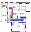
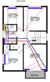
I am looking to make my boiler heat as well and as efficiently as possible. I have drawn up a diagram of possible pipe runs (sorry, I know its a bit rough).
I plan to take the flow (red on drawing) and return (blue on drawing) in 22mm (thick lines on drawing) and use T pieces to take 15mm (thin lines on drawing) spurs of off each to feed the radiators (the purple blobs on my drawing, which are not to scale, are radiators and their locations).
I will also leave a couple of blank 15mm tails on the ground floor in the hall heading for the garage for a possible future garage conversion.
Am I right in thinking that it is most beneficial to take the pipes as far as possible in 22mm and then take 15mm off of them as needed?
I am a novice at this sort of thing. So any help or suggestions would be gratefully appreciated. Please don't hold back if you see any glaring errors. The most important thing for me is for my heating system to work well (nice and warm) but also as efficiently as possible.
Please see attached drawings. Questions welcome. Thanks.
Attachments
Last edited:


