Pyronix Paragon Super - No Codes???

Joined
29 May 2022
Messages
14
Reaction score
0
Country
United Kingdom
Hello all,

I am really hoping that you can help…

I have recently bought a house that I am renovating to move into. There is a Pyronix Paragon Super alarm system installed.

I do not have any codes, and cannot contact the seller for them.

I have downloaded the annual and have tried using the standard user code (5678), master code (1234) and engineer code (9999) but none of them seem to register on the alarm, so I assume they were changed at some point.

Does anyone have any advice as to how I can reset the alarm codes back to the factory ones?

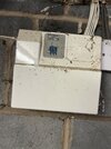
As I do not know any of the codes, if I open the RKP pad or the alarm box the whole internal and external alarm system goes off for a while as it thinks it’s being ‘tampered with’. I can’t stop this manually without knowing the codes. (It’s now flashing alarm and tamper too in red since I set it off).

I’ve added some pictures in the hope someone can help!

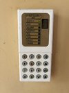
You can see on the keypad that the numbers 1,3,5,0 are dirtier so I assume the code is made up of these digits… but who knows!
 

Attachments

  • 77ED7387-51B1-47AE-815B-B42662BCAA7A.jpeg
    77ED7387-51B1-47AE-815B-B42662BCAA7A.jpeg
    247.9 KB · Views: 259
  • E8D8DA85-C1F9-44FA-AB0E-18E1A9C9F15B.jpeg
    E8D8DA85-C1F9-44FA-AB0E-18E1A9C9F15B.jpeg
    373.6 KB · Views: 175
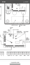
Power down put a link on the nvm reset pins and power back up …..the control panel will need reprogramming
 

Attachments

  • 9F7FDC72-F8D3-4417-BC1A-1418E50A7E7C.png
    9F7FDC72-F8D3-4417-BC1A-1418E50A7E7C.png
    306.5 KB · Views: 237
Also dependent on age of control panel,early panels didn't have reset pins, and you had to hold 1+4 on power up.
Post photo of pcb if unsure.
 
Thanks for the replies so far. Just a few questions:

1) If I have to link the NVM reset pins together, is there a specific type of cable/wire I would need to use? It it just a case of holding the wire against the pins whilst someone turns the power back on (with battery disconnected)?

2) when the control panel needs reprogramming - this is just for the user selections (e.g alarm cut off time, entry/exit time). Is that right? I know the codes will reset, but what else? Will the zones still be programmed?

3) if I turn the power off at the mains, hold 1&4 and get someone to turn the mains on, is this an alternative for the above (or for just if there are no pins)? This isn’t mentioned in the manual.

4) if I remove the cover and the tamper alarm starts going off, would unplugging the battery silence this?

The house was built in 1998 so alarm components are circa 24yrs old.

Thanks all - alarms aren’t my forte.
 
Last edited:
Shorting the pins with a screwdriver will work.
Defaulting the panel to factory settings eg 30 sec entry exit timer, bell 20 mins etc.
You may need to program each zone to your setup from keypad to exit door

Your may not need to hold 1+4 down if you have reset pins

Taking control panel cover off will cause internal sounder to dound tamper fault,once defaulted you can direct with user code.
 
Thank you for this, really helpful.

So just so I’ve got the order right in my mind, the steps are:

1) turn off electricity at the mains
2) open the large box with the battery in it
3) disconnect the battery
4) place a short on the pins (screwdriver/wire etc)
5) turn electricity on at the mains
6) alarm should be going off, so enter factory codes to disable alarm on RKP panel (1234 or 5678)
7) if worked, remove short on board, reconnect battery and shut up the box
8) timings etc need resetting and potentially zones
9) relax

Is there anything I’ve missed or need to consider, please?
 
Replace battery if it’s more than 5 years old and think about replacing that alarm in the next few years
 
Good shout - thanks.

I am happy with the location of the panels, sensors and RPK panel, would it be possible for an installer to use the existing wiring and simply replace the sensors and the pcb etc and wire up to a new system?

Of course I’ll ask the installer the question but just to give me an idea if it’s do-able this way?
 
Hello all - sorry to resurrect this thread.

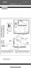
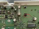
Where are the NVM pins on this pcb? The manual diagram shows separate mains fail disable pins and nvm reset link, but on the circuit board I can only see 4 pins these could relate to?

Which are the NVM pins that I need to short together on restart to set the system back to factory settings?

Thanks!
 

Attachments

  • 33792A17-8459-4ED0-BD43-3812D8C7D0EC.png
    33792A17-8459-4ED0-BD43-3812D8C7D0EC.png
    261 KB · Views: 108
  • 3A4BE105-BFD5-4CDA-B96B-2500AA7AD92B.png
    3A4BE105-BFD5-4CDA-B96B-2500AA7AD92B.png
    1 MB · Views: 120
Bottom two ? If not try top two ….
 

Attachments

  • FC351608-061F-4932-9673-F2D6812B3AD6.jpeg
    FC351608-061F-4932-9673-F2D6812B3AD6.jpeg
    422.3 KB · Views: 89
Was thinking that as the obvious, but not sure of the risks associated with shorting the wrong parts of the PCB? As I don’t have the jumper supplied with the board, what alternative can I use? Was thinking of some copper cable or a screwdriver?

The diagram is spot on with the location of the other components, so seems strange that it’s a bit out for these? Maybe that’s just me?
 
none as the other set ( if shorted continually) stops you setting it in a mains fail situation…..a small screwdriver flat blade will normally do the trick !
 
Thanks for that - and just to confirm that the below is the correct order?

1) turn off electricity at the mains
2) open the large box with the battery in it
3) disconnect the battery
4) place a short on the pins (flathead screwdriver)
5) turn electricity on at the mains (with screwdriver shorting both pins)
6) alarm should be going off, so enter factory codes to disable alarm on RKP panel (1234 or 5678)
7) if worked, remove screwdriver shorting the board, reconnect battery and shut up the box
8) timings etc need resetting and potentially zones
 
Back
Top