Replacing Honeywell ST7100 with hive.

Joined
24 Oct 2017
Messages
8
Reaction score
0
Country
United Kingdom
Hi all,

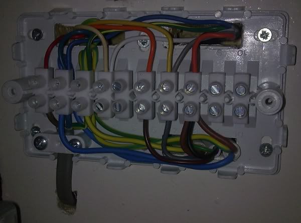
Purchased a hive and as i have an oil fired Benson Jetstream boiler, BG will not install. Here's what the wiring of the old back plate looked like.

What it boils down to is:
Wire 1 containing:
(1L) - A brown live wire coming from a fused spur, currently connected to the L.
(1N) - A blue neutral coming from the same fused spur, currently running up to the blue block in the top left
(1E)- An earth coming from the same fused spur running up to the earth block in the top left

Wire 2 containing

(2L) - A brown wire coming from the down into the guts of the boiler (can't see more as access is poor, currently wired to 5 (CH on).
(2N) - A blue neutral currently running up to the blue block in the top left
(2E) - An earth coming running up to the earth block in the top left

Wire 3 containing

(3L) - A brown wire coming from the down into the guts of the boiler (can't see more as access is poor, currently wired to 8 (HW on).
(3N) - A blue neutral currently running up to the blue block in the top left
(3E) - An earth coming running up to the earth block in the top left

Wire 4 running to the existing room stat, which i plan to isolate entirely from the system and remove from the walls.

My plan is to wire as follows:

1L to the L terminal of the hive
1N to the N terminal
1E to the Earth tether
2L to the 4 terminal
2N to the N terminal
2E to the Earth tether
3L to the 3 terminal
3N to the N terminal
3E to the Earth tether


I am by no means an electrician, but if it is as simple as that, then please let me know. If there is something fundamental that i am misunderstanding then please let me know and i will call a pro.

I26ncoB.jpg
abc-png.112402
 
Are there currently 2 wires in CH on? That sounds about right, but you will need to transfer all the old wiring into a wiring centre then run a new 5 core cable from the Hive to the wiring centre.
 
Yes as per the original wiring shown above there were two wires going into CH on.

Thanks for you help, much appreciated, just to clarify, by the wiring centre you mean the main fuse box for the entire house?

Doesn't the hive receiver just connect to the mains via the live connection at the existing spur? Then it handles distribution of that live feed to either the hw or ch? Where would the five core sit in that system?

I have wired it up as per my description above so if you can clarify what you think needs to change let me know.

I am also very confused by the pipe set up, this is the first time we have had to turn on the heating since we bought it and I am not seeing any 3 port or zone valves at all. Further inspection of the wiring shows that the HW wiring goes down to the oil pump and the CH wiring goes to a single grundfos super selecteric pump as attached.

There is no other wiring coming from the old controller, so I assume that means there can be no other vales hidden away as there would be no way to switch them on/off.
15088876870101243559688.jpg
15088877771862023818080.jpg
15088871489851029806314.jpg
 
Here's my current status...Hive is wired in as described above and with the Hive set to gravity fed system. Hot water fires up fine independently and when CH is scheduled it fires on both the hot water light and the CH. However, upstairs radiators are the only ones getting hot. My thinking is that perhaps for whatever reason when i request CH, the hive sends the command to the boiler to fire up, the rads nearest to the outlet pipe of boiler get heated because of their proximity to the boiler but the downstairs don't as the pump is not working.

Does that seem like a reasonable explanation? If so does this suggest that the Hive wiring is not correctly powering up the pump? If so any suggestions beyond the wiring shown above? Or is it more likely the pump itself is faulty? I have tried manually turning the pump spindle and it seems to turn relatively freely. Is there anything else i can do to diagnose the problem? Could i simply wire the pump to the mains directly via a plug and see if that causes it to start pumping to the downstairs rads?
 
By wiring centre I mean a new central heating junction box to contain the large number of wires.
Example:
TEF111-1.jpg

If there was 2 wires in CH on before the same 2 wires need to be connected to CH on now.
Where is all the other wiring now? in you first photo there are loads of cables, but in the new hive backplate only 3?
 
Besides the 3 core going to the old wall stat (now entirely removed) and the 3 wires mentioned, all other wiring shown in that photo was purely internal within the old controller, running between one terminal or another. I assumed the function of these wires was replicated by the hive controller in some other way.
 
Besides the 3 core going to the old wall stat (now entirely removed)
When you "removed" the old thermostat, did you reconfigure the wiring to take into account its absence? If you just remove the wires, then the heating wiring (ie that controlling pump) will be 'open circuit' and never come on. The two wires that previously went to the switching contacts at the thermostat need to be joined together.

That would explain your symptoms of the upstairs radiators heating up by natural circulation but the ground floor radiators don't as the pump isn't running.
 
Ah, my understanding of the Hive system was that when the wireless thermostat decided it was too cold, it would tell the controller/receiver to close the circuit running from terminal 4 of the new backplate to the pump, i.e. the physical wire between the wall thermostat and the controller had been replaced by the wifi link between the new stat and receiver.

If that's not the case, any hints about what is missing, if i remember correctly i think the wiring from the old wall stat ran to the old receiver via the black wire at 5. The other two cores ran to the top left neutral and earth blocks and no other wires from the stat went anywhere else.
 
Unfortunately these systems are all wired differently, depending upon the layout of the components in relation to the property and the personal preferences of the installer.

Previously you had two devices controlling the heating which were wired in series; in that both the room stat and the programmer had to be 'on' for the pump to run. The Hive does both functions and is wired in place of the programmer, however the old thermostat would have still been wired in series with it, so just removing it, leaves the pump wiring open circuit.

If you can't remember where the original thermostat cable went, you will need to trace the wire that comes from terminal 4 'heating on' of the Hive and find the other end of it. That will be one of the original thermostat connections. The other thermostat connection would have been the live to the pump.

In the end what you want to achieve is that the above connections are linked together so that terminal 4 of the hive is now connected to the pump live.
 
If you can't remember where the original thermostat cable went, you will need to trace the wire that comes from terminal 4 'heating on' of the Hive and find the other end of it. That will be one of the original thermostat connections. The other thermostat connection would have been the live to the pump.

That's what's confusing me, as far as i remember, the wire now coming from the 4 terminal originally ran directly to the water pump, and the wire that was the running from the thermostat ran only to the old controller, at terminal 5 with nothing from the stat connecting directly to the pump.

I realise that doesn't make sense as then how is the stat supposed to have any affect on whether the pump turns on or not, so either my memory is faulty or the thermostat was previously not wired correctly. When we moved in, we just checked that the boiler fired up and heated the rads throughout and kind of ignored anything else, so i can't say for sure that the thermostat ever actually worked!

Despite the problems i must say heating systems are a really fun (and probably dangerous) convergence of plumbing and electrics!
 
You will need to trace the wiring to be sure, but here's a simplified sketch what I would have expected to have found as regards the central heating wiring. It makes my waffle a bit easier to understand.

Original installation
1.jpg

What I think you have now. ie Hive added and original room thermostat removed
2.jpg

What you should end up with
3.jpg
 
OK Thanks for the effort! I will take a look at your drawings and have a think. Having checked the remains of the old controller pictured, from which I only removed the wires mentioned above (3 core direct to spur, 3 core direct to boiler (HW on) and 3 core direct to pump (CH on)).

I am struggling to work out how it fits with the drawings you provided. I can see (I think), how the spur provides current to the terminal L on the old controller which travels via the brown wire to the CH com terminal and down the red wire to the stat, which will only pass current onto CH on at terminal 5 via the black wire if the stat switches on.

What I still don't get is that now that this controller and stat is remove, there seems to be no break in the circuit besides that controlled by the Hive controller. Current would run from the spur, down to the hive, then the hive decides based upon a signal from the wireless stat to either provide current to terminal 4 or not. This wire is and always had been directly wired to pump with no interruptions in between and so when it has current it should power the pump. It isn't so obviously I have cocked something up!
 

Attachments

  • IMG_20171026_181131.jpg
    IMG_20171026_181131.jpg
    307.9 KB · Views: 788
It looks like the stat was wired in parallel rather than the normal series, so either the timer or the room stat could switch on the heating so your wiring should work. Have you checked the pump spins freely with a screwdriver? It may be stuck if it hasn't been used in a while.
upload_2017-10-26_21-52-28.png

Ignore the bit about opening the isolation valves.
 
Last edited:
Ok thanks, that was really useful, checked pump when hive was supposedly running central heating, the internal shaft was not rotating. However, i then wired the pump directly to the mains and what do you know the shaft starts spinning. Therefore I guess there might be a problem with how I have it wired, although I can't see a problem myself.
15088871489851029806314.jpg
 
Back
Top