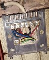
Replacing Horstmann C17 confused by existing wiring

Joined
19 Jul 2022
Messages
6
Reaction score
2
Country
United Kingdom
Intending to replace elderly in-laws boiler Horstmann C17 timer with a Hive wireless thermostat but confused by the existing wiring.

The boiler is a Biasi Riva OV but has a strange setup in that it has no external thermostat and a manual heating/hot water diverter valve (Servowarm valve).

Due to memory problems she is struggling with the existing controller so the intention was to replace with a Hive so that we can remotely ensure the house is at a comfortable temperature.

The odd bit in the C17 is an apparent live link to terminal 4 (red wire photo attached). In the photo the lead entering on the left is from the fused switch and the lead on the right goes to the boiler, you can see that they cross over in the mounting plate.

The Biasi instructions state that any external equipment should be volt free.

The thing is this setup is currently working quite happily and has been for 15 years+

Can anyone offer any thoughts as to what is going on with this set-up?
 

Attachments

  • 20220719_181658.jpg
    20220719_181658.jpg
    471.7 KB · Views: 129
I don’t know why there’s a link to 4, unless it’s to bypass a failing programmer or the switch live and boiler live are wired differently. Someone else might be able to confirm. You may also have a C plan setup. Can you post a photo of the cylinder cupboard?
 
I don’t know why there’s a link to 4, unless it’s to bypass a failing programmer or the switch live and boiler live are wired differently. Someone else might be able to confirm. You may also have a C plan setup. Can you post a photo of the cylinder cupboard?
Can't get a photo at the moment but here's a pic of the type of diverter valve fitted. The valve is manual operation, there are no electrical connections to the cylinder or valve.
1D73D613-7917-4170-A1A1-5219DAAAC203.jpeg
 
Can't get a photo at the moment but here's a pic of the type of diverter valve fitted. The valve is manual operation, there are no electrical connections to the cylinder or valve.View attachment 274879
Ok, my apologies, you did mention this, and I’ve only heard of it once previously (on a discussion on here). You need one of the more experienced engineers.
 
, if you want to fit a hive and have full control you will have to swap the piece of crap servowarm valve with a 3 port mid position valve and alter the wiring, possibly some plumbing too, that sytem you have was a cowboy way install cheap at the time but a total waste of energy and not acceptable these days
 
, if you want to fit a hive and have full control you will have to swap the piece of crap servowarm valve with a 3 port mid position valve and alter the wiring, possibly some plumbing too, that sytem you have was a cowboy way install cheap at the time but a total waste of energy and not acceptable these days
Appreciate that but the intention for now is a quick-fix by just replacing the existing timer so that we can monitor and remotely regulate the temperature for her.
 
Does she have a boadband router ?
Yes. Setting up a Hive itself will be a doddle. Problem is working out what is going on with the existing setup on the Horstmann C17 as it is definitely not one of the more standard setups.

Terminal 2 should be boiler live (and according to the Biasi instructions volt free) but what is controlling the switching to the boiler?
Ignoring the permanent live and neutral connections to the boiler there would only seem to be the one wire to the boiler so t2 must be acting as a switched live.
Normally t4 would be switched live. Seems almost to be wired back to front with power going to t4 via the link wire which presumably would be opened to t2 when the internal timer switch kicks in?
yes you are correct, the Horstmann switches betwee 2&4 yours is back to front but doesnt really matter, it is just a switch and will work, single channel hive will work if you put the wire in 2 existing to 3 on the hive and link L&1 on the hive , but it wont work if the servo is set to Hot water
 
yes you are correct, the Horstmann switches betwee 2&4 yours is back to front but doesnt really matter, it is just a switch and will work, single channel hive will work if you put the wire in 2 existing to 3 on the hive and link L&1 on the hive , but it wont work if the servo is set to Hot water
Thanks ianmcd, nice to have my thinking validated.

So switching the link wire to t2 and taking the switched live from t4 would work the same on the C17 then.
On the hive (single channel receiver) it would be switched live on t3 and a link from live to t1

Still not sure why the controller is wired at 230v when the Biasi says external controllers should be volt free but as it's been wired this way with only 4-core cable since installation and not caused any problems then I can't see it doing any harm to wire the hive the same way?
 
Volt free doesn’t mean no voltage whatsoever, it means the voltage is supplied by whatever the user wants it to be, have a look here to perhaps understand it better.
 
Volt free doesn’t mean no voltage whatsoever, it means the voltage is supplied by whatever the user wants it to be, have a look here to perhaps understand it better.
Understand that thanks.

The Biasi instructions state "If a programmer/room thermostat is to be fitted remove the red link between L1 and L3 and connect the device across these terminals. Any external controls fitted must be rated at 230V 50Hz and have volt free contacts." - which typically means separation from the main supply wiring.

Your comment did however prompt me to re-read the instructions and I also found this "The appliances may be used with any certified mains voltage room thermostat"

So inconsistency in the instructions but maybe that answers the question as to why there is mains voltage going to the boiler, although it's a timer not a thermostat at the end of the day it is just a switch.
 
So inconsistency in the instructions but maybe that answers the question as to why there is mains voltage going to the boiler, although it's a timer not a thermostat at the end of the day it is just a switch.
yes you are correct , the problem with Biasi and a lot of other manus instructions is the origional MIs would be in the language of the country of origin and when they get translated to English some get mixed messages, happens a lot. the reason for voltage free switching contacts is so that different controllers can be used, some switch 24 V some mains some even weird voltages, volt free allows you to use what the boiler requiers, so always best practice to use the two terminals at the boiler to go to the 2 switching wires at the controller if voltage free, that way you cant damage the boiler, in your case it is switching mains voltage but has been all this time so wont make any difference
 
Back
Top