Safely dismantling light fixtures (capping wires)

Joined
25 Sep 2023
Messages
5
Reaction score
0
Country
United Kingdom
Hello all,

First off, apologies if this question is the very basics and has been answered several times. As a novice to DIY, I just wanted to double check that my planned approach to dismantling a light fixture is the safest/correct approach -- I just can't seem to find anything clear on Youtube specific to the UK unfortunately.

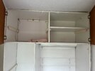
We're wanting to take down the wardrobe in the image attached, which would involve dismantling the light fixture. The light is powered by a wall switch. Rather than have this fixture dangling from the wall, I plan to dismantle the casing and cap off the wiring. This would be intended as a temporary solution before bringing in an electrician in a month or two for a batch of various jobs.

What I had in mind:
1.) Test Voltage pen works on known live wire and a known wire that is off
2.) Turn off mains power to property (in our case we have an older consumer unit which doesn't specify per-room supply)
2.b.) Tape down wall switch off, just in case.
3.) Remove bulb/tube and dismantle outer light casing (I'm sure I don't need the mains power off for this but just in case)
4.) Test Voltage pen again on exposed wire in question to triple check it is off.
5.) Feed wires through a junction box
6.) Use electrical tape to cap off the ends of each wire. For a fixture like this I imagine there would be 3 wires, with the start of the loop instead occurring at the switch. However ... here's where I'm confused ... if there are 6 wires (2 x live, neutral, earth), am I supposed to cap off each wire individually; or connect each corresponding wire via a two-way connector e.g. wago? I probably wouldn't trust myself just yet with the latter.
7.) Make sure the junction box is secured
8.) Turn mains back on

Please do call me out on anything stupid or any major omissions in that list. I'm open to halting my plans and waiting on the electrician if needs be.

Thanks,

Danny
 

Attachments

  • IMG_0900.jpg
    IMG_0900.jpg
    205.4 KB · Views: 66
What sort of voltage pen? The non-contact ones for tracing/finding wires aren't suitable for testing a circuit is dead before carrying out work.
 
What sort of voltage pen? The non-contact ones for tracing/finding wires aren't suitable for testing a circuit is dead before carrying out work.
Thanks for your response!

Admittedly, I haven't bought this yet. I was going to get this non-contact one from Fluke (https://www.screwfix.com/p/fluke-ac-non-contact-voltage-detector-pen-1000v-ac/85949), but now looking at the reviews perhaps not.

Please do advise what the appropriate device would be (digital multi-meter ?) and any recommended brands.

Just for context, I can't imagine routinely doing electrical jobs myself around the house. So probably up to about £70 is what I'd want to be spending upfront on a device. If anything under that amount really isn't worth it then it's probably best for me to wait it out for an electrician.
 
Agreed, a cheap multimeter should suffice.

I do use non contact "pens" but additionally use a multimeter between live and neutral.

The non contact pens can be useful but (because of induction) they can give false positives. A false positive however is better than a false negative...
 
Show us a pic of your consumer unit, and the switch that controls that light fitting.
 
6.) Use electrical tape to cap off the ends of each wire. For a fixture like this I imagine there would be 3 wires, with the start of the loop instead occurring at the switch. However ... here's where I'm confused ... if there are 6 wires (2 x live, neutral, earth), am I supposed to cap off each wire individually; or connect each corresponding wire via a two-way connector e.g. wago? I probably wouldn't trust myself just yet with the latter.

On a very temporary basis, and assuming there are no kids etc. about, then I would suggest taking it slowly, a little at a time, using choc blocks or even better wago connectors, don't join them with tape, though tape will not harm over the connectors.

Take photos before you start, then move all of one set of joined wires, into your new connectors or wagos, before moving to the next set. All wires that were joined to one terminal, will need to all be joined when you have done, or you may find other lights do not work when you have finished.
 
Show us a pic of your consumer unit, and the switch that controls that light fitting.

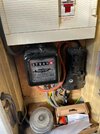
I won't be back at the property for a number of days so will have to get back to you on that for an image of the two. The consumer unit is a Memera 2000 RCD ... could well be this one (https://willrose-electrical.co.uk/p...a-double-pole-80a-rccb-memera-2000-a80he-new/) ... hopefully this old meter reading offers some clues also.

We do intend to upgrade to something more modern soon.
 

Attachments

  • IMG_0601.jpg
    IMG_0601.jpg
    285.6 KB · Views: 59
On a very temporary basis, and assuming there are no kids etc. about, then I would suggest taking it slowly, a little at a time, using choc blocks or even better wago connectors, don't join them with tape, though tape will not harm over the connectors.

Take photos before you start, then move all of one set of joined wires, into your new connectors or wagos, before moving to the next set. All wires that were joined to one terminal, will need to all be joined when you have done, or you may find other lights do not work when you have finished.

Thanks for the advice -- no kids or animals fortunately.

I'm happy to completely detach/isolate any other fixtures on that ring temporarily. I'm just looking for a safe temporary solution for 'disabling' the wiring to that light fixture so that we can continue with decorating the room, before getting in an electrician.

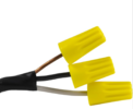
I'm likely poorly communicating my intentions here, I do not intend to use electrical tape to connect wire-to-wire but instead to isolate each wire so that there is no risk of wires being exposed to each other. Similar to the first image -- though using electrical tape rather than US style wire nuts. I know this will cause a break in the ring, but would there be any negatives consequences of doing this? I can't actually find any images for the *UK way* of doing this, so maybe this just isn't a done thing (?) I understand that doing this doesn't mean that these wires can be completely ignored as there could still potentially be a power supply to these wires -- just that they are contained safely.

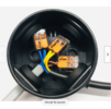
I believe most suggestions have been to "complete" that ring using connectors as in the second image. I believe I understand this would be the best bet to make sure other fixtures work in the room, however I'm not used to recutting wires to expose the correct amount of tubing in the connector -- which I imagine could be a risk in itself if I do a shoddy job.
 

Attachments

  • isolated.PNG
    isolated.PNG
    378.1 KB · Views: 55
  • connected.PNG
    connected.PNG
    815.4 KB · Views: 48
Thanks, it should be using the upstairs lighting circuit -- I was confusing terminology there -- though I shouldn't make any assumptions. I imagine if this is the case then each light fixture should be connected to a junction box/switch through a single light cable so that all I need to do is isolate the 3 exposed wires at the end of that light cable (?)
 
It could be wired as a spur from a power circuit ,and the switch a switched FCU. ( Hence asking for a pic of the switch earlier)
It looks like the light fitting was an add on ,and it's anyone's guess as to what circuit it's on.
It appears that one cable only goes to the fitting ,in which case it should be a simple disconnection ,and safe termination of conductors into wagos and enclosure.
 
Back
Top