Secondary Grundfos ups2 on vr66 - wiring question

Joined
8 Sep 2023
Messages
54
Reaction score
0
Country
United Kingdom
Hi All

S-Plan with two MRVs (CH and DHW). Valves are controlled by a Vaillant wiring centre. When calling for CH the CH valve opens and boiler fires, all good.

How do you connect a CH water pump (type grundfos) to this wiring centre? It has a live neutral and earth but if all connected to 230v it's going to run constantly while it should only run when there is a call for CH.

Should it connect to the same L, N and E of the CH valve so that they get the same live and operate at the same time? If yes I assume it's a wago box situation in order to keep it all tidy and not to plug both the MRV and the CH pump in the same block on the vaillant wiring centre?

Many thanks

EDIT (to clarify): this is about an external pump on the pipework, in addition to the boiler internal pump.
 
Last edited:
Most boilers provide a dedicated connection for the pump. This is because the pump is required to run for a few minutes after the heating has gone off to distribute residual heat and prevent the boilers overheat tripping. To achieve this, the boiler has to control it, and many boilers have the pump built in and pre wired.

With boilers that don't need a pump overrun, the pump is wired to the boiler so that whenever the boiler runs, the pump does too, when the boiler goes off the pump does too.

S-Plans are fully pumped, so the pump is required for both CH and DHW. If you were to connect the pump to the LNE of the CH motorised valve, it would only run when the heating was on, and not operate when you just wanted DHW.
 
Last edited:
How do you connect a CH water pump (type grundfos) to this wiring centre? It has a live neutral and earth but if all connected to 230v it's going to run constantly while it should only run when there is a call for CH.
Wrong you say you have an S plann so pump has to run for HW only and for CH, what boiler do you have
 
Thanks Both,

This is for a Vaillant Ecotech 637 plus, unvented external cyl, two MRVs and the grundfos.

When setup in relay mode with a classic junction box the grundfos gets to operate when told to do so by the programmer. With a Vaillant wiring centre there is no block for external grundfos, only for 230v, cyl, CH valve, DHW valve and ebus (and ntc if you use this, not the case here).

Thanks
 
Should it connect to the same L, N and E of the CH valve so that they get the same live and operate at the same time? If yes I assume it's a wago box situation in order to keep it all tidy and not to plug both the MRV and the CH pump in the same block on the vaillant wiring centre?

The pump is normally connected to the dedicated terminals inside the boiler, so the boiler controls the pump. So it can run the pump, after the boiler has stopped it's burn, to remove the last of the heat from the boiler.
 
When setup in relay mode with a classic junction box the grundfos gets to operate when told to do so by the programmer. With a wiring centre there is no block for external grundfos, only for 230v, cyl, CH valve, DHW valve and ebus (and ntc if you use this, not the case here).

Exactly, you need to connect the pump, direct to the boiler - via new, separate cable.
 
Exactly, you need to connect the pump, direct to the boiler - via new, separate cable.
Thanks Harry, with a classic junction box there is a cable going from the 230v RT block on the boiler PCB to the junction box and controls near the valves and cylinder (say an airing cupboard).

With a wiring centre it's different, there is the ebus going from the PCB on the boiler to the wiring centre (situated in the airing cupboard) ebus block. The thermostat can then be wired to the wiring centre also on the ebus block.

Is there a way to connect the grundfos to the wiring centre (arguably a lot easier as the pump is near the wiring centre and valves) or does it absolutely have to get wired to the PCB of the boiler which is located elsewhere? You'd think vaillant thought about this and got a way to avoid another cable run just for the pump especially whilst the wiring centre does open and close the MRVs so should be able to tell when the pump runs....

Thanks
 
The installation manual I have for the 'Vaillant ecoTECH 637 Plus' shows it with a pre wired internal pump. Is yours different?

Screenshot 2023-11-27 115459.png
 
Is there a way to connect the grundfos to the wiring centre (arguably a lot easier as the pump is near the wiring centre and valves) or does it absolutely have to get wired to the PCB of the boiler which is located elsewhere? You'd think vaillant thought about this and got a way to avoid another cable run just for the pump especially whilst the wiring centre does open and close the MRVs so should be able to tell when the pump runs....

No, you have to run the extra cable, as is true for most/all modern boilers with overrun. Going to the boiler, you have permanent mains supply, ebus pair, and pump supply.

If you originally had old, fully wired controls, you might be able to reuse those old cables. In my case, it was able to reuse the original mains supply at a local isolator, for both the boiler, and the VR??, but I found it easier to run a new ebus pair, and pump cable, via the gap behind my kitchen coving, from kitchen boiler, up to airing cupboard.
 
The installation manual I have for the 'Vaillant ecoTECH 637 Plus' shows it with a pre wired internal pump. Is yours different?

View attachment 322789
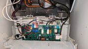
You're right Stem, there is an internal pump which is connected to the PCB on the x18 connector (green block next to 230v block).

I'm talking about an additional, external grundfos pump which is placed on the pipe work near the valves. I guess this was placed to improve the flow (11 rads two floors) and get the return temp up. This was connected in a junction box and got a live when the valves open.

With a wiring centre unsure how to plug that in. If it now has to go to the PCB it would most likely go on the X16 (optional connector visibly for a pump according to manual) but that would need to be confirmed, and also it would be a bummer as it would need a new cable run. Sounds like a headache whilst there is already a cable run for the ebus to the wiring centre.
 
Last edited:
From an electrical point of view, then what has been said already will still apply, assuming that you can access the pump terminals and the boiler's control circuitry is strong enough to support two pumps.....

It's unusual for a system the size of yours to have 2 pumps though. I have 12 rads and one pump that's running on its lowest speed and it works fine and the same set up does for countless other installations. Two pumps sounds very strange to me but I'm a sparky, so I think one of the central heating gurus will have to take this one over........but at least you now know why the Vaillant VR66 doesn't have a connection for the pump.
 
PCB photo added. As you can see the internal pump is in. It's the external grundfos that has to operate when the valves open that is not plugged. Before ebus and wiring centre there was a 230v brown block with the grey cable which has you see is now disconnected and this was going to the junction box.

All works well otherwise, just trying to get that external pump connected.
 

Attachments

  • 1000018406.jpg
    1000018406.jpg
    267.9 KB · Views: 77
If the external pump were connected to the same LNE as the internal pump they would both operate together. But I would still want confirmation that the boiler pump control circuit is capable of driving two pumps together without damage, and still question the need for two pumps in the first place.

Also to be considered is a by-pass to allow the pump to run on for a few minutes once both motorised valves have closed and there's no water flow through them. The boiler has an internal by-pass, so the internal pump will be OK, but what about the external pump, does it have an external bypass?

If you are sure that the CH is the only part of the system to use the second pump, and the boilers internal pump will run the DHW, then you could wire the second pump to the CH motorised valve.

Just as an after thought, you're not having a boiler without an internal pump replaced by one that does are you, hence the introduction of a second unnecessary pump?

EDIT
I'm talking about an additional, external grundfos pump which is placed on the pipe work near the valves. I guess this was placed to improve the flow (11 rads two floors) and get the return temp up.

That's not good for a condensing boiler, the idea is to get the return flow temperature as low as possible.
 
Last edited:
Thank for your input, much appreciated!

Here is additional info and a photo of the pipe work of this install:

- I'm positive there is already an internal pump in the ecotec plus boiler (as you'd expect). It is a Vaillant / Grundfos UPM3 and it's wired on the PCB on the X18 connector. There are two pumps on this installation: one in the boiler, and the UPS2 pump on the pipework.

- I'm almost certain the UPS2 pump on the pipework was wired so that it would operate only if the CH valve was in open position. A wire from the thermostat was on the same block as the brown of the CH motorised valve. There was no connection between this external pump wires and the DHW motorised valve. The DHW motorised valve was operating as you'd expect (if thermostat calls for DHW and then if CYL stat calls for heat then DHW valve opens and the microswitch turns the boiler and internal boiler pump on, the external pump did not seem involve for DHW).

- This is the pipework of this S-plan:
flowchart annotated.jpg


It's not visible in the photo but after the DHW valve the pipe that goes down is the flow for DHW going into the cylinder, and DHW then goes out from the output pipe following the red arrows.

As you can see the external (additional / UPS2) pump is on the primary flow pipe coming from the boiler BEFORE the motorised valves. So if the CH valve was opened, the pump would run as well, if the DHW valve was opened but not the CH (e.g. in the summer to get hot shower) the pump would not operate, but the water would pass through anyway.

Here is my first question: would that pump on the primary flow pipe being turned off hinder the flow because of the blades inside it and make it harder for the boiler internal pump to get the water moving? I assume this would not be an issue since it was working like this, but it begs the question ..

Now as far as I can see, there is no by-pass valve on this pipework. So in the eventuality of that external pump running and both valves being closed the water had nowhere to go and that pump would struggle and overheat (as @stem mentioned above). I assume this simply never happened because the wiring was done so that the pump would only operate if the CH valve was opened.

However here is my second question: by default the boiler internal pump is meant to overrun ~5 minutes after the flame is off. Is there a setting that keeps at least one valve opened whilst that internal pump is running? If not where would the water pumped by the internal pump go during this 5 minutes overrun? As @stem said there is indeed an internal by-pass valve within the boiler however unsure how much pipe circuit there is for the water to flow and hence how effective those internal by-pass actually are?

Keen to have your views on this set-up. It works I guess... but starting to wonder if this was installed as it should have.
 
Last edited:
would that pump on the primary flow pipe being turned off hinder the flow because of the blades inside it and make it harder for the boiler internal pump to get the water moving? I assume this would not be an issue since it was working like this, but it begs the question ..
There will be some resistance, but I would imagine overall it probably has a greater cross section than the 22mm pipe it's connected to, although it could generate some turbulence. Hard to say really and although I've helped with 100's of systems, this is the first domestic installation I've ever come across with more than one pump. (Other than underfloor heating systems) As it was, the only time the external pump wasn't running was when the HW only was operating, and that requires a much lower flow than the CH, probably more like the flow required by a single radiator.

Now as far as I can see, there is no by-pass valve on this pipework. So in the eventuality of that external pump running and both valves being closed the water had nowhere to go and that pump would struggle and overheat (as @stem mentioned above). I assume this simply never happened because the wiring was done so that the pump would only operate if the CH valve was opened.
OK. When you first asked the question about how to wire the pump, you hadn't mentioned there was another internal pump [having said that I've since noticed that the title of your post refers to it as a secondary pump :rolleyes:] so the initial comments you got back were based on the external pump having to pump the HW circuit as well.

From an electrical point of view. If the external pump was wired to the CH MV, then there's no problem with it not having a by-pass as it won't be running once the valve has closed.

by default the boiler internal pump is meant to overrun ~5 minutes after the flame is off. Is there a setting that keeps at least one valve opened whilst that internal pump is running? If not where would the water pumped by the internal pump go during this 5 minutes overrun? As @stem said there is indeed an internal by-pass valve within the boiler however unsure how much pipe circuit there is for the water to flow and hence how effective those internal by-pass actually are?
It circulates the water around inside the boiler. Don't worry about it though it's designed to do it by the manufacturer, if there was a problem it would be tripping the boilers overheat function.

Keen to have your views on this set-up. It works I guess... but starting to wonder if this was installed as it should have.
Like I said my skills are really electrical; my plumbing knowledge I've picked up as I've worked alongside others, so I would be interested to know why there are two pumps on your system. Perhaps you would consider starting a new thread with the title 'why do I have two pumps' or something similar, giving details of your set up. This thread has a controls bias so some of the expert plumbing engineers on here won't be following the discussion, and a new thread might just pique their interest.
 
Back
Top