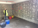
wiring in an insulated floor - do I have a problem?

Joined
20 Oct 2022
Messages
6
Reaction score
1
Country
United Kingdom
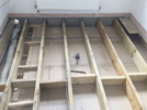
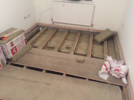
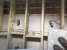
So I had several floors in my house insulated because of sound problems , I didn't realise at the time that the builders, as far as I can tell from pics I took at the time, have surrounded wiring in the floor with insulation (RW45). In particular, I think the main trunks of wiring going through the centre of joists has been surrounded, as you can see in the pics (before and after). I've searched a bit for this and it seems like if you are in America its not a problem, but if you're in the UK, it is a problem. Should I be worried? And if so , what can I do? The floor (chipboard T&G) has been glued and screwed down in all the rooms.
 

Attachments

  • IMG_9178.png
    IMG_9178.png
    2.5 MB · Views: 140
  • IMG_9196.png
    IMG_9196.png
    2.8 MB · Views: 133
Completely surrounding cables with thermal insulation reduces their current-carrying-capacity by 50% so could well be a problem on all but the lighting circuits.
 
Completely surrounding cables with thermal insulation reduces their current-carrying-capacity by 50% so could well be a problem on all but the lighting circuits.
What can I do about this? I have no idea where to start.. the builder who did this will not answer my calls. Is this a case of taking the ceiling down in all the rooms to remove insulation around the cables? I think I know where most of the main bits of cable are enclosed but I doubt I can locate it all
 
Most of the cables visible (the smaller ones) do seem to be lighting circuits so they will be alright - 16A cable on 6A circuits.

Other than that there just appear to be two larger cables running across the picture.
Can you tell what they supply from their location? They do look like socket circuit cables - not large enough for shower or similar.

If they are just upstairs sockets then, without dismantling the floors, you could have the likely 32A MCB for the circuit reduced to a 16A MCB. This will still be adequate for bedrooms etc.


However in the OP you said several floors so there could be other cables involved.
 
As regards with insulation around electric cables - they don't seem to teach this at builder school...
 
Most of the cables visible (the smaller ones) do seem to be lighting circuits so they will be alright - 16A cable on 6A circuits.

Other than that there just appear to be two larger cables running across the picture.
Can you tell what they supply from their location? They do look like socket circuit cables - not large enough for shower or similar.

If they are just upstairs sockets then, without dismantling the floors, you could have the likely 32A MCB for the circuit reduced to a 16A MCB. This will still be adequate for bedrooms etc.


However in the OP you said several floors so there could be other cables involved
The pics above were of the lounge floor, which is above a basement kitchen. The cables you can see, I think you're right they are just for electrical sockets and lighting. There are bedrooms above the lounge but they only have regular electrical sockets and there is no electric shower, so maybe they're ok if I used a 16 amp MCB. (the sockets are on a 32A MCB)

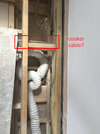
Unfortunately I think there is a cable to the cooker that comes in the hallway then cuts across the lounge floor, at the other end of the room from the pics above. You can see it below cutting left to right in the lounge floor, and then coming down the wall in the kitchen to the cooker switch.

Does that look like the cooker cable in the lounge floor to you? If so, what are my options - should I cut up into the kitchen ceiling and cut away the insulation around the cooker cable?
 

Attachments

  • IMG_9111 edit.jpg
    IMG_9111 edit.jpg
    319.5 KB · Views: 105
  • IMG_9191 edit.jpg
    IMG_9191 edit.jpg
    286.6 KB · Views: 113
  • IMG_9535 edit.jpg
    IMG_9535 edit.jpg
    380.4 KB · Views: 87
Last edited:
That coiled fan flexi-duct looks like it's going to collect water that can't drain away.
 
The sad thing is that insulation doesn't make a lot of difference to sound transmission as it tends to go through the joists (ask me how I know!).
 
It does look like it might be a cooker circuit cable, but -

Normally cooker circuits are 6mm² cable with 32A MCB.

6mm² T&E has a maximum current-carrying-capacity of 47A so worst case scenario of 50% derating is 23.5A.

However, with cooking appliances, which have many separate elements cycling on and off even though switched on, we apply "diversity".
This is the first 10A of the total current plus 30% of the remainder.

So - even with a 12kW cooker which is 50A, it works out at 40 x 0.3 + 10 which is 22A (+ 5A if you have a socket on the switch).
Therefore you could (without socket) swap the 32A MCB for a 25A one - although that won't actually reduce the actual current used as 25A breakers do not instantly trip at 25.1A but technically it would likely be satisfactory.
My cooker is 2.99 KW total connected load
Energy consumption per cycle in conventional mode:0.97 kWh
Energy consumption per cycle in fan-forced convection mode:0.81 kWh

This sounds promising but also like I need an electrician…
 
Last edited:
Back
Top