Any hope lighting circuit?

Joined
16 Nov 2012
Messages
10
Reaction score
2
Location
Lancashire
Country
United Kingdom
Hi all, after 8 years of having a house extension done I've got round to buying and installing an outdoor light. The wire to outside was put in when the extension was done and terminated in a three-gang switch. Two switches control internal lights (on 2-way switching) and the third was there to control outside.

There was a single wire to outside and I've wired that up (Live to live, Neutral to neutral, earth to earth) - easy so far... I come inside to wire up the switch and realise there's no 'supply' as such. Just the single wire in from outside.

I've tried tracing each of the existing wires to try and understand what's there, but left worrying there's no easy way to get power to the external light without tearing into walls and adding in an extra wire (Something my wife's not going to allow!).

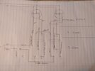
I've tried cobbling together a wiring diagram- is there any hope in reconfiguring the existing wiring to get power to the outdoor light? Not too bothered about having the two existing internal lights on seperate switches, so if they can be re-wired and repurposed, happy to give it a go!

Any thoughts greatly appreciated!
1000015859.jpg
 
Hi all, after 8 years of having a house extension done I've got round to buying and installing an outdoor light. The wire to outside was put in when the extension was done and terminated in a three-gang switch. Two switches control internal lights (on 2-way switching) and the third was there to control outside.

There was a single wire to outside and I've wired that up (Live to live, Neutral to neutral, earth to earth) - easy so far... I come inside to wire up the switch and realise there's no 'supply' as such. Just the single wire in from outside.

I've tried tracing each of the existing wires to try and understand what's there, but left worrying there's no easy way to get power to the external light without tearing into walls and adding in an extra wire (Something my wife's not going to allow!).

I've tried cobbling together a wiring diagram- is there any hope in reconfiguring the existing wiring to get power to the outdoor light? Not too bothered about having the two existing internal lights on seperate switches, so if they can be re-wired and repurposed, happy to give it a go!

Any thoughts greatly appreciated!View attachment 351127
Mostly, when new-users post on these sites, there is not enough "information" given.
In this case, there may be "Too Much" and, at the same time "Not Enough".

You wrote
"The wire to outside was put in when the extension was done and terminated in a three-gang switch. Two switches control internal lights (on 2-way switching) and the third was there to control outside."
where "wire" should have been written as "cable".

The Left Hand side of your diagram may be trying to indicate that which you are trying to convey.

If there is a "three-gang switch"
with one switch "not doing anything"
and
an incoming "one pair and earth" Cable coming in from the "outside light",
all that should be necessary is to
connect the "Line" (Brown) conductor from the "Common" on one of the other switches to the "Common" of the unused switch
and
connect the Switched-Line (Brown) conductor for the external light to "L1" of that switch
plus
connect the Neutral (Blue) conductor to the other Neutral conductors at that location.

Photos of the "Three-gang" switch wiring box and connections may be of assistance.
 
Took me a moment or two to parse that diagram on a sunday morning, but got there (I think!)

So your T/E for you new outside light goes back to a three gang switch, the other two ways are two way-ed with three cores in the conversion method from a two gang switch that has the swicth drops from two lights on the same cirucit at it?

The problem as you have relised is that you have no neutral at the three gang switch, but as long as you are sure all the lights are on the same cirucit, you should be able to get one. You have four cores from fittings to the 2 gang switch and have two unswitched lives and again in the three cores two are unswitched lives so you have more cores than you strictly need.
 
Show us a pic of all wiring connections at the 3 gang switch,and any present in its mounting box behind.
Was the outside light cable connected to anything at the switch location ?
 
Too much and too little - trying to be helpful, but obviously missed the mark! Engineer by trade but by no means an electrician!

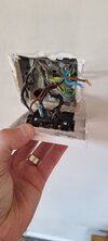
I've added some photos of the three-gang switch - as both @FrodoOne and @Adam_151 have asked, they're definitely on the same circuit - all lights downstairs are on one RCD.

This is the 'Left switch' on the original diagram and the two wires loose are the ones from outside.

So if I connected a brown 'jumper' wire from the 'Left switch - middle: common' to 'Left switch - Right: common' that'd get me my live.

Connect outside brown to 'Left switch - Right: 1-way'.

Then finally, the outside blue to 'Left switch - middle: 2-way', that should get me my neutral?

Reading that back I get how it's massively confusing; especially early Sunday morning!

The help is massively appreciated!

The fact there's hope had made my morning!
 

Attachments

  • 20240803_170202.jpg
    20240803_170202.jpg
    136.7 KB · Views: 45
Have you looked at the wiring present at the other switch locations ( the remote locations) ? Unless the original installer has dropped a clanger ,the twin and earth cable that you refer to as the outside light cable doesn't go directly to the outside light as you think.
 
Have you looked at the wiring present at the other switch locations ( the remote locations) ? Unless the original installer has dropped a clanger ,the twin and earth cable that you refer to as the outside light cable doesn't go directly to the outside light as you think.
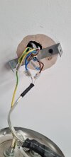
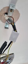
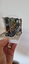
Attached photos of the two light roses and the other switch. As far as I can tell (rudimentary continuity test) the wire from outside twin + earth is literally that.
 

Attachments

  • 20240803_171531.jpg
    20240803_171531.jpg
    131.6 KB · Views: 38
  • 20240803_171002.jpg
    20240803_171002.jpg
    87.5 KB · Views: 32
  • 20240803_170218.jpg
    20240803_170218.jpg
    101.1 KB · Views: 32
Just as an aside to this, remove the two unused mounting screws that are still clipped onto the back of the switch faceplate just I case they come loose at some stage in the future and drop and short out the connections.
 
You're all true gentlemen (and ladies? - don't want to presume!) for the advice. I think the fact there's hope means I might get a professional in to tackle it as I don't want to mess anything up.

Thanks for all the advice - greatly appreciated!

P.s. @Sureitsoff? - spare screws removed
 
You could do this, remember to sleeve appropiatly as one grey is a line and the other is a neutral
Unless I'm misreading the original. I don't understand Adams drawing, I think nothing needs doing at the 2G or a grey repurposed.

In left light: Alter the blue to neutral;
1722782659110.png

In 3G switch; Move blue to a connector as neutral, add 2 jumpers and insert brown to '1W';
1722782739298.png


Excuse me for 'flipping' some symbols:
1722779693222.png
 
Last edited:
@SUNRAY has understood the current situation differently to me, I understood it as both the switch drops went to the 2 gang switch, and then there were two 3cores wired conversion method to 2 gangs of the 3 gang switch that he wanted to use the remaining switch for an outside light. Rather than one switch drop to each end, I think hes right looking at the pictures of the existing, but I was trying to understand original drawing
 
Back
Top