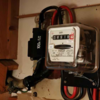
Fuse panel hot unit, smell in corridor below?

With bigger systems there are often different arrangements. I know it's deviating from the sort of system we are considering - but consider metering on the 11KV part of the system where there are just 3 wires feeding a substation, the only way to record usage is to measure the current and voltage of each phase individually. Admittedly one will not be using a straightforward meter we are accustomed to but the format remains the same by using current transformers on each phase conductor and a voltage transformer across two phases. Commonly down to say 20A and 110V
needless to say, such situations are beyond my experience, but I still don't see how it relates to 'the three neutral terminals' on a meter, and what one would connect them to (if no neutral were available0 - and, as I said, if a neutral (one neutral) were available, then I don't see why one would need (or 'know what to do with!) three neutral terminals on the meter.

Sorry if I'm being dimn!

Kind Regards, John

[QUOTE="SUNRAY, edit]No, one Neutral reference terminal per phase, only used as a voltage reference point. [/QUOTE]
Not comprehending something is not the same as being dim.

upload_2021-6-18_20-32-34.png
I assume measuring the voltage and current makes sense to you.
 
Last edited:
No, one Neutral reference terminal per phase, only used as a voltage reference point.
Well, it was you, not me, who started this by writing "... one 2KA I saw had 3 individual N terminals" :)

However, I still don't really understand. If you are suggesting that each of the three "Neutral reference terminals" should be externally connected to one of the phase conductors to provide a 'voltage reference' for the power determination, then (a) how does one know which terminal to connect to which phase and (b) why is that not just done internally, within the meter, without the need for any terminals or external connections?

Kind Regards, John
The thing about 3ph is there are variations on formats such as star / delta and rather than have a variety of different metering devices they may be 'adaptable'.
Single phase is easy:
upload_2021-6-19_0-57-54.png
measure V & I and multiply together.

This is then repeated for all 3 phases
upload_2021-6-19_1-47-56.png


but if the neutral is not available the reference is a phase:
upload_2021-6-19_1-0-25.png
Ensuring the phase rotation is maintained

In a delta connected load this may look like this:
upload_2021-6-19_1-17-20.png
Where the load is shown as pink.
Ideally the current is measured in each branch Shown I etc but this is not always available on it's own and will have to be measured at I red etc. The corresponding voltage is easily measured at each end of the load between the point the current is measured and the reference lead connected to the most appropriate place such as the next phase.

Obviously if there is a neutral in the system, that is unboubtedly the best reference point.
upload_2021-6-19_1-59-25.png

I hope not but I've probably made it more confusing now
 
Thanks for the update - that sounds fairkly promising.
Sorry - these things do happen. However, the situation is fairly intriguing, and I therefore wonder whether it might be possible for you to provide the additional photo that I've mentioned, so that we could put a lot of the speculation to bed??

Kind Regards, John

Can you send a clearer photograph of the main supply cable, ie the thing on the left of your original picture
?

As requested, hope this is clear enough...

Fusebox n Meter 5.jpg

I also attach a cryptic message left in my father's handwriting (actually recopied in mine cos original was slick with black liquid - see below)...

Fusebox n Meter 4.jpg

And finally... in case the original purpose of this thread has been forgotten :rolleyes:... A piccie of the inside of the doorbell transformer unit.

Fusebox n Meter 3.jpg

Doesn't look in bad shape to my untrained eye? Well, apart from the black staining of the inside of the unit's cover, that is...


P.S. In case the presence of baking paper becomes another major sub-thread... I put it in that spot as a precaution as there was previously dark fluid underneath the black wiring on the left - you can see where a little of the black isolation tape droops down, as if melted. Don't know when or why this happened... I cleaned it up, put baking paper in case of future drips but it hasn't re-occurred since.
 
Last edited:
And by the way, eSure Home Insurance's Emergency Cover doesn't cover electrical stuff! How useful is that?! There's a reason this optional cover was offered to me for free...

Can I do the replacement (if it's necessary) of the doorbell transformer myself? Just shut off mains supply, remove screws, bung in a similarly-sized transformer? Do these things ever overheat to the point of burning stuff?

Answers on a postcard. :confused:
 
[QUOTE="Propah Charlie, post: 4991895, member: 289471]

Can I do the replacement (if it's necessary) of the doorbell transformer myself? Just shut off mains supply, remove screws, bung in a similarly-sized transformer? Do these things ever overheat to the point of burning stuff?
[/QUOTE]
Yes you can replace it yourself. But you need to find out why it is overheating. They don’t normally overheat by themselves. If it is a faulty cable say, a replacement will also overheat.
 
As requested, hope this is clear enough...

View attachment 236791

I also attach a cryptic message left in my father's handwriting (actually recopied in mine cos original was slick with black liquid - see below)...

View attachment 236792

And finally... in case the original purpose of this thread has been forgotten :rolleyes:... A piccie of the inside of the doorbell transformer unit.

View attachment 236793

Doesn't look in bad shape to my untrained eye? Well, apart from the black staining of the inside of the unit's cover, that is...


P.S. In case the presence of baking paper becomes another major sub-thread... I put it in that spot as a precaution as there was previously dark fluid underneath the black wiring on the left - you can see where a little of the black isolation tape droops down, as if melted. Don't know when or why this happened... I cleaned it up, put baking paper in case of future drips but it hasn't re-occurred since.


Nice one. Thanks. Doorbell transformers do sometimes get warm. Do you use your doorbell? Does your doorbell work? A jammed bell push can cause a transformer to fry.

***

Your house appears to be wired correctly, no obvious reversed polarity, and the last five pages - as far as you're concerned at least - was a waste of time.

While we got hold of you, going back to my original comment all those pages ago, is that black cable ok?

In your picture it looks a bit funny.

In the top left of your picture just check the where the black cable emerges from the black service head. In the picture it looks like it could heat damaged.

It is probably and hopefully a trick of the light.
 
Last edited:
Your house appears to be wired correctly, no obvious reversed polarity, and the last five pages - as far as you're concerned at least - was a waste of time.
That's obviously true from the OP's point of view, but I would personally say that, for some of the rest of us, the discussion has been interesting, educational and, in at least one sense, has reminded us of a salutary lesson (see below). To be fair (to myself!), I did point out fairly early on that "that a 'straight on' photo would settle [it] once and for all" - and such a photo would certainly have avoided a lot of the subsequent speculation.

I would say that the "salutory lesson" is that we have all (certainly myself) been reminded of how misleading 'optical illusions' can be. I have to say that, even now that I am able to look at the photos 'side by side' (below), I find it "hard to believe" that the situation is "as it is" on the basis of what we saw in the initial photo. If I were a betting man, I think I would probably have put money on the fact that the right-hand branch of the incoming supply was heading somewhere significantly to the right of the fuse holder - and certainly not to an entry to that fuse holder on it's bottom left !

Of course, none of us would have had reason for a moment's thought had we be been there in person - but, as far as remote activities in a forum are concerned, the moral surely has to be "beware of photos"!

Chunky19 deserves credit for having worked it out before anyone else, but Sunray's suggestion (which I considered 'unlikely' on the basis of the photo) wasn't too far off, either.

upload_2021-6-19_14-43-5.png
upload_2021-6-19_14-43-19.png


Kind Regards, John
 

Attachments

  • upload_2021-6-19_14-41-45.png
    upload_2021-6-19_14-41-45.png
    95.8 KB · Views: 62
  • upload_2021-6-19_14-42-15.png
    upload_2021-6-19_14-42-15.png
    117.9 KB · Views: 70
P.S. In case the presence of baking paper becomes another major sub-thread... I put it in that spot as a precaution as there was previously dark fluid underneath the black wiring on the left - you can see where a little of the black isolation tape droops down, as if melted. Don't know when or why this happened... I cleaned it up, put baking paper in case of future drips but it hasn't re-occurred since.

The black is probably leaking sealing bitumen sealing compound from the lead armoured cable.
 
"Chunky19 deserves credit for having worked it out before anyone else" Thank you JohnW2
You're welcome - but I was merely observing an obvious truth. Well done - particularly given that, as I recently wrote, I personally struggle to 'see the truth' from that original photo, even now that I know what I'm looking for!!

Kind Regards, John
 
Back
Top