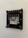
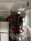
I picked up some fuses but it still blows, makes a lovely electrical burning smell too. Certainly needs a new PCB. Their engineer is coming Saturday and they know it is suspect so he'd better have a pcb on the van. Hopefully he can wire in the Drayton hub too. Had a horrible thought that i'd reversed the L and N wires, but I checked and I still think the wiring is fine. Bit of a mystery tbh! Turns out some things are best left to the pros!
You are using an out of date browser. It may not display this or other websites correctly.
You should upgrade or use an alternative browser.
You should upgrade or use an alternative browser.
Ideal Instinct PCB
- Thread starter andyp187
- Start date
-
- Tags
- #draytonwiser boiler instinct pcb
Had a horrible thought that i'd reversed the L and N wires,
That would not be the cause.
Had a horrible thought that i'd reversed the L and N wires,
That would not be the cause.
Thanks Harry, that does make me feel better! Your tip about the guaranteed repair was a good one too. While more money than I wanted to pay it seems like the best bet at this stage. The ROI on my smart heating might be a year longer than i'd hoped!
Thanks Harry, that does make me feel better! Your tip about the guaranteed repair was a good one too. While more money than I wanted to pay it seems like the best bet at this stage. The ROI on my smart heating might be a year longer than i'd hoped!
It beats buying and fitting a pcb, only to find there is another fault taking the pcb out.
The overheated section on the PCB are the connections to the gas valve.
Although I don't know the failure mode of the gas valve, this may also be something for your engineer to check, before plugging in a new PCB.
Although I don't know the failure mode of the gas valve, this may also be something for your engineer to check, before plugging in a new PCB.
Given the location I'd say it's almost certainly a bridge rectifier enabling the gas valve to be energised with DC (ie. rectified 240 V mains) so before having a new pcb fitted check the gas valve solenoid resistance (and to earth).
Could my wiring of the Drayton controller done it? This is what I had. Live coming from the brown and the two switching wires going to the room stat terminals on the ideal boiler. I have seen one picture of a single switching wire coming from the Drayton but their instruction seems to suggest there should be a switched live and return
Attachments
that link between L&1 should not be there, in pic one you have the N coneected to a grey wire then in pic the grey wire is connected to the live wire, when did you move them ?Could my wiring of the Drayton controller done it? This is what I had. Live coming from the brown and the two switching wires going to the room stat terminals on the ideal boiler. I have seen one picture of a single switching wire coming from the Drayton but their instruction seems to suggest there should be a switched live and return
Last edited:
The link between L & 1 would only be required if there was a similar link on the Salus. Do you have a picture of your Salus wiring. Note your comment "Power needs to be put on to terminal 1 either by linking from L or a sperate supply", that's the grey wire for your system which is the separate supply.
The Wiser installation instructions are not very clear for a 1-channel installation. Often a Combi boiler will have voltage free switching which I suspect is your situation. In your case the function of the 1-channel Wiser hub is to "join" terminals 1 & 3 together when on and "disconnect" when off. The Wiser itself needs 240V power but that only goes to L & N. Effectively there is electrical isolation between L/N and 1/3.So the live is coming from the grey switch wire? There was no link on the salus RF itself. There was a link between the room stat terminals in the boiler


