Recommendations for New Oil Burner - Equivalent to Riello G2SX (419T55)

OK, I have the same 530SE control Box and took a few readings, the first thing I should mention in case I forget it is I think there are two types of photocell, digital& analogue?, mine measures 434/3890 ohms light/nolight so maybe compare your old and new with this.

Other readings (terminal box)
Between terminals and ohms
1-2 1450 (coil)
1-8 1442 (coil)
2-3 OC
3-6 3.37K (I think)
3-7 8.4 (motor)
6-E 161 (capacitor)

photocell 434/3890 with light/light blanked off.

There are 3 wires going to the coil, blue/brown/black so maybe closing winding and hold in winding?
 

Attachments

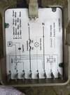
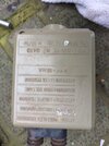
  • My 530SE Control Box Bottomside.jpg
    My 530SE Control Box Bottomside.jpg
    213.6 KB · Views: 131
  • My 530SE Control Box Topside.jpg
    My 530SE Control Box Topside.jpg
    220.1 KB · Views: 73
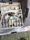
  • My 530SE Terminal wiring.jpg
    My 530SE Terminal wiring.jpg
    262.5 KB · Views: 113
Just for information.
Today I was fitting a Grant boiler house model burner is supplied separately in a riello box. Included in box 2 manual for burner.
Picture is page 23 of manual.
As you can see Riello look to be recommending most parts are changed at 10 years!
20231114_141946.jpg
 
I'm eight years overdue so, not one item has required changing on my Riello G5X apart from service items like fuel nozzles and flexible fuel lines and I'm certainly not unique in this, fuel pumps are probably the most frequently changed, mainly because the tank is let run dry and then even worse some try to get them to refire after a refill by repeated resetting of the combustion failure.
 
Let us know how you get on as I am curious about the cause in case I suffer the same.

I don't think the control box requires the photocell to be working before starting the ignition cycle which it does not appear to be doing.

Like @Johntheo5 I have had a Riello burner for 15 years without needimg to replace anything except pump, hoses or nozzles, and the previous owners left me with their service records ditto going back to 1996. Motor bearings were a bit noisy so I replaced them as a precaution though.
 
In the very unlikely event you need to reset the electrode gap, under no circumstances try to bend them. If you slacken off the nuts at the back, you can rotate them to the correct position.
As you have replaced every component that can cause continuous running without lockout, it is difficult to make any other suggestion. If you can hear the solenoid open, and it carries on running, then you would get a pool of oil in the combustion chamber.
Are you sure you are not getting constant reignition due to fumes . I've often seen this on older boilers with poor seals around the burner gasket or the access covers.
 
OK, I have the same 530SE control Box and took a few readings, the first thing I should mention in case I forget it is I think there are two types of photocell, digital& analogue?, mine measures 434/3890 ohms light/nolight so maybe compare your old and new with this.

Other readings (terminal box)
Between terminals and ohms
1-2 1450 (coil)
1-8 1442 (coil)
2-3 OC
3-6 3.37K (I think)
3-7 8.4 (motor)
6-E 161 (capacitor)

photocell 434/3890 with light/light blanked off.

There are 3 wires going to the coil, blue/brown/black so maybe closing winding and hold in winding?
A typo above, its 1 to 2, brown to blue = 1450 ohms and 8 to 2, black to blue, is 1442 ohms so obviously 230V to pull in the coil and maybe 50V hold in voltage, so worth at least checking those terminal connections, it might be possible to monitor the hold in voltage somehow when the boiler is running?, stick a pin into either the blue or brown wire, at the coil and check both voltages with a M.meter?
 
I can now confirm with the help of my wife's small darning needle that the coil holding voltage is 54V via terminal 8 and the black wire, as shown in the schematic.
Its a bit surprising IMO that while it takes 230^2/1450, 36.5watts to close the valve it only requires 54^2/1450, 2.0watts to keep it closed.
 
Last edited:
Correction re coil resistances, black wire to blue is 1.7 ohms re my M.meter but per manufacturer 1.4 ohms) I'm told that during ignition 30V DC is supplied to the brown (1450 ohm) and 3VDV is supplied to the black wire (1.4 ohm). I,ve no idea why I'm getting 54VAC on this circuit, can't get any DC reading on any of the DC scales.
 
I can now confirm with the help of my wife's small darning needle that the coil holding voltage is 54V via terminal 8 and the black wire, as shown in the schematic.
Its a bit surprising IMO that while it takes 230^2/1450, 36.5watts to close the valve it only requires 54^2/1450, 2.0watts to keep it closed.
Correction re coil resistances, black wire to blue is 1.7 ohms re my M.meter but per manufacturer 1.4 ohms) I'm told that during ignition 30V DC is supplied to the brown (1450 ohm) and 3VDV is supplied to the black wire (1.4 ohm). I,ve no idea why I'm getting 54VAC on this circuit, can't get any DC reading on any of the DC scales.
With boiler/ running, as well as the apparent 54VAC on the black wire (1.4 ohm),I also measured (today) 4.74VDC on the brown (1450 ohms) ,wire this means that IF this is the holding voltage then the coil power is 4.74*4.74/1450, 0.0155 watts, if one ignores the apparent 54VDC on the black wire then it means that the closing power, at ignition conditions is 30^30/1.4, 642.9 watts. Doesn't make much sense to me.

If 4.74VDC was feeding the black (1.4 ohms) (closing wire) at ignition conditions then the closing power is, 4.74*4.74/1.4, 16 watts
and if 30VDC was feeding the brown (holding wire) wire then the holding power is, 30^30/1450, 0.62 watts. This makes far more sense but not what I am measuring.
The manufacturers figures are 30VDC & 3.0VDC and 1470ohms (brown) & 1.4ohms. (black) which is more or less what I measured, (resistance readings)

I am told that the replacement burner for the Riello G2SX is the Riello G5X.
 
Last edited:
I ran 3 flying wires out of the terminal box bottom from 1, (brown wire), 2, common blue from the coil and 3 from 8 (black wire)

On start up I get 25VDC from the black wire (8) immediately on start up and this voltage remains there throughout the firing cycle. 12 secs after start up, pre purge. I get 5VDC on the brown (holding wire), 0 VDC up to this 12 sec which is correct. If I probe from the coil common (2) I get a continuous 25VDC from start up to finish.

This is not correct, to prevent oil dribbling out of the nozzle as the fan/oil pump motor is running up, the NO oil valve restricts the the pressure to below 5 bar and returns this recirculated oil to the tank, 12 secs after the prepurge is complete 25/30VDC should be supplied from the black wire, probably at the same time (by my stopwatch ) 5V is also spplied to the brown wire (this allows the oil pressure to rise to 8bar to 10bar running pressure) BUT the 25/20VDC to the black wire should then be switched out to the coil. Also if 25VDC is supplied to a 1.4omh coil then the power, theoretically is 446watts, probabl OK for a few seconds but not continuously.

I also get 54VAC as well as the 25VDC on the black wire and 24VAC as well as 5VDC on the brown wire while energised.

I also removed the burner from the boiler and ran it for 4 consecutive 9 sec periods, stopping it before each 12 sec prepurge elapsing/ignition, 36 sec in all, I couldn't see any sign whatsoever of a oil dribble from the burner which one would think should happen if the solenoid valve is energized from the very start.
 
Apologies for my delay in reply and thank you to everyone for all the suggestions.

I've quickly tested the solenoid coil for resistance this evening and get the expected 1.3 ohms from the starting circuit on terminals 2 & 8 of the sub base and the expected 1350 ohms from the running circuit on terminals 1 & 2. The metal cover is fitted in the correct position and as far as I can tell it's functional. I'm assuming the the needle valve which it operates would cause a lockout if it were stuck?

The 2 different photocells tested slightly different for resistance, but both have a low reading under light and a high reading in the dark. As they're performing as expected, my assumption is they're also functional. The fact the control box won't lockout when it's removed also suggested it's not the photocell. I can't say if they are analogue or digital units, but as one is the original I would say the new unit is compatible.

I can hear something "click" after around 9 seconds, but I'm no longer confident it's the solenoid, so I'll need to test to see if it's being energised.

I've noticed after removing the new control box following an attempted start that one side is noticeably warm, but I don't get this with the old unit?

Is this likely to be an issue with the ignition transformer in yet another faulty control box?

I'm confident there's no attempt at ignition, as I can't see any light through the flame observation window and there's no characteristic buzzing of the electrodes. I haven't checked the spark gap, but would this lead to a condition where the fan runs continuously without going to lockout? I'll remove it from the oil line tomorrow just to rule this out, but I'm not hopeful.

The fan motor can be made to run continuously by bridging terminals 5 & 6 on the sub base - will a control box that's dead or faulty make this connection regardless of it's condition?

It's a shame we don't have a firing sequence for the control box to understand the electronic side a bit better.

polygraph.
 
You might consider doing the following sometime like what I did.
Connect 3 flying wires (short lengths of cable) out of the terminal box bottom from 1, (brown wire), 2, common blue from the coil and 3 from 8 (black wire)
Connect your M.meter between 8 and earth, start up the boiler, check that you get 25/30VDC immediately and until the burner either trips or keeps running.
Next connect M.meter between 1 and earth, start the boiler, on boiler start up you should get 0VDC, if the ignition sequence continues long enough (in my case 12 secs, the puge period) you should then get 3 to 5VDC.
Finally connect M.meter between 2 and earth, start the boiler, you should get 25/30VDC immediately on start up and until the burner either trips or keep running.
Even though I don't fully understand why (1) you get any voltage until purge is complete and (2) why I get 25VDC apparently continuously between 2 and earth as one would think that pin 2 must, at some stage connect to neutral, so voltage between 2 and N should then be zero, it doesn't really matter because my burner works flawlessely with the above sequence.
 
Right, finally got around to reporting on the solenoid voltages.

Original Grey Control Box

Terminal 1 Brown Wire to Earth.
Start @ 23v >>> 10 seconds >>> finish @ -22v

Terminal 2 Blue Wire to Earth.
Start @ 23.2v >>> 10 seconds >>> finish @ 22.2v

Terminal 8 Black Wire to Earth.
Start @ 23v >>> 10 seconds >>> finish @ -22v

New White Control Box

Terminal 1 Brown Wire to Earth.
Start @ 22.8v >>> 8 seconds >>> finish @ -21.8v

Terminal 2 Blue Wire to Earth.
Start @ 23.2v >>> 8 seconds >>> finish @ 22.2v

Terminal 8 Black Wire to Earth.
Start @ 22.9v >>> 8 seconds >>> finish @ -21.9v

Both control boxes appear to be behaving in the same way, although I'm not sure about the negative finishing values on terminals 1 and 2?

My multimeter was set to 200v DC with the black common probe to earth and the red probe to each terminal, so hope that was correct.

Each unit has a small difference in time between switching voltages on terminals 1 and 8. Another difference is the audible "click" you hear when these voltages change. The white unit produces this click after 8 seconds, but the grey one doesn't make any noise at all.

The Riello fault finding diagram suggests I should be seeing 27-30v DC at the coil at ignition, dropping to 3v DC on running.

My starting voltages are around 5v lower and they don't drop to 3v.

Could both control boxes be faulty in exactly the same way? Seems unlikely.

I'm completely stumped now and will probably have to give in and order a Riello R40 G5X Oil Burner, 21-26 kW.

polygraph.
 
Last edited:
Right, finally got around to reporting on the solenoid voltages.

Original Grey Control Box

Terminal 1 Brown Wire to Earth.
Start @ 23v >>> 10 seconds >>> finish @ -22v

Terminal 2 Blue Wire to Earth.
Start @ 23.2v >>> 10 seconds >>> finish @ 22.2v

Terminal 8 Black Wire to Earth.
Start @ 23v >>> 10 seconds >>> finish @ -22v

New White Control Box

Terminal 1 Brown Wire to Earth.
Start @ 22.8v >>> 8 seconds >>> finish @ -21.8v

Terminal 2 Blue Wire to Earth.
Start @ 23.2v >>> 8 seconds >>> finish @ 22.2v

Terminal 8 Black Wire to Earth.
Start @ 22.9v >>> 8 seconds >>> finish @ -21.9v

Both control boxes appear to be behaving in the same way, although I'm not sure about the negative finishing values on terminals 1 and 2?

My multimeter was set to 200v DC with the black common probe to earth and the red probe to each terminal, so hope that was correct.

Each unit has a small difference in time between switching voltages on terminals 1 and 8. Another difference is the audible "click" you hear when these voltages change. The white unit produces this click after 8 seconds, but the grey one doesn't make any noise at all.

The Riello fault finding diagram suggests I should be seeing 27-30v DC at the coil at ignition, dropping to 3v DC on running.

My starting voltages are around 5v lower and they don't drop to 3v.

Could both control boxes be faulty in exactly the same way? Seems unlikely.

I'm completely stumped now and will probably have to give in and order a Riello R40 G5X Oil Burner, 21-26 kW.

polygraph.
Probably best to invest in a burner, my tests on my perfectly working burner don't make sense either as the starting voltage doesn't seem to drop off after the holding voltage of 5V energise 12 secs after start up,, also the RCD trips if you probe between 8&2 or1,&2 with the M.meter set to 200VDC.
 
Back
Top